


7
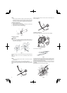
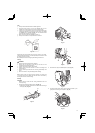
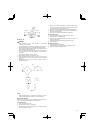
Installation of blade guard (Fig. 9, 10)
NOTE
The guard bracket may come already mounted to the gear case
on some models.
Install the blade guard on drive shaft tube against angle
transmission. Tighten the guard bracket fi rmly so that the blade
guard does not swing or move down during operation.
Install the blade guard to the guard bracket, which also secures the
guard to the gear case using the two guard mounting screws.
Fig. 9
Fig. 10
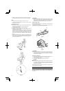
CAUTION
Some blade guards are equipped with sharp line limiters. Be
careful with handling it.
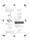
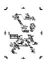
When using a trimmer head with two piece type blade guard, attach
the guard extension to the blade guard. (Fig. 11)
Fig. 11
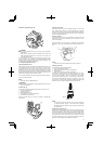
NOTE
○ When attaching the guard extension to the blade guard, the
sharp line limiter must be removed from the blade guard, (if so
installed).
○ If your unit has guard location label on drive shaft tube, follow
the indication.
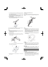
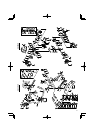
○ To remove the guard extension, refer to the drawings. Wear
gloves as the extension has a sharp line limiter, then push the
four square tabs on the guard one by one in order. (Fig. 12)
Fig. 12
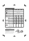
Installation of semi-auto cutting head
1. Function
Automatically feeds more nylon cutting line when it is tapped at
low rpm (not greater than 4500 rpm).
Specifi cations
Code No.
Type of
attaching screw
Direction of
rotation
Size of
attaching screw
6696454 Female screw Counterclockwise M10×P1.25-LH
6696597 Female screw Clockwise M8×P1.25-RH
Applicable nylon cord
Cord diameter: Φ3.0 mm Length: 2 m
Cord diameter: Φ2.4 mm Length: 4 m
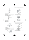
2. Precautions
○ The case must be securely attached to the cover.
○ Check the cover, case and other components for cracks or
other damage.
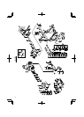
○ Check the case and button for wear.
If the wear limit mark (17) on the case is no longer visible or
there is a hole in the bottom (18) of the button, change the new
parts immediately. (Fig. 13)
18
17
Fig. 13
○ The cutting head must be securely mounted to the unit’s gear
case.