


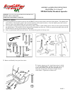
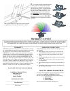
11. Install handle shaft to lower handles and pivot & bracket assembly as shown. Using (4) 1 ½” bolts and (4) locknuts.
Tighten bolts and nuts now.
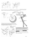
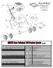
12. Install (1) 1/4-20 regular nut (not a locknut) on to con-
trol rod as shown.
13. Install flattened end of control rod in to lever on gauge as
shown. Turn to lock in place. Next push lever forward to setting
“0”. Align control rod with hole in pivot bracket, pull lever
backward to insert control rod through hole in pivot bracket.
Now install 1/4-20 regular nut on to control rod. DO NOT
TIGHTEN NUTS YET.
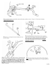
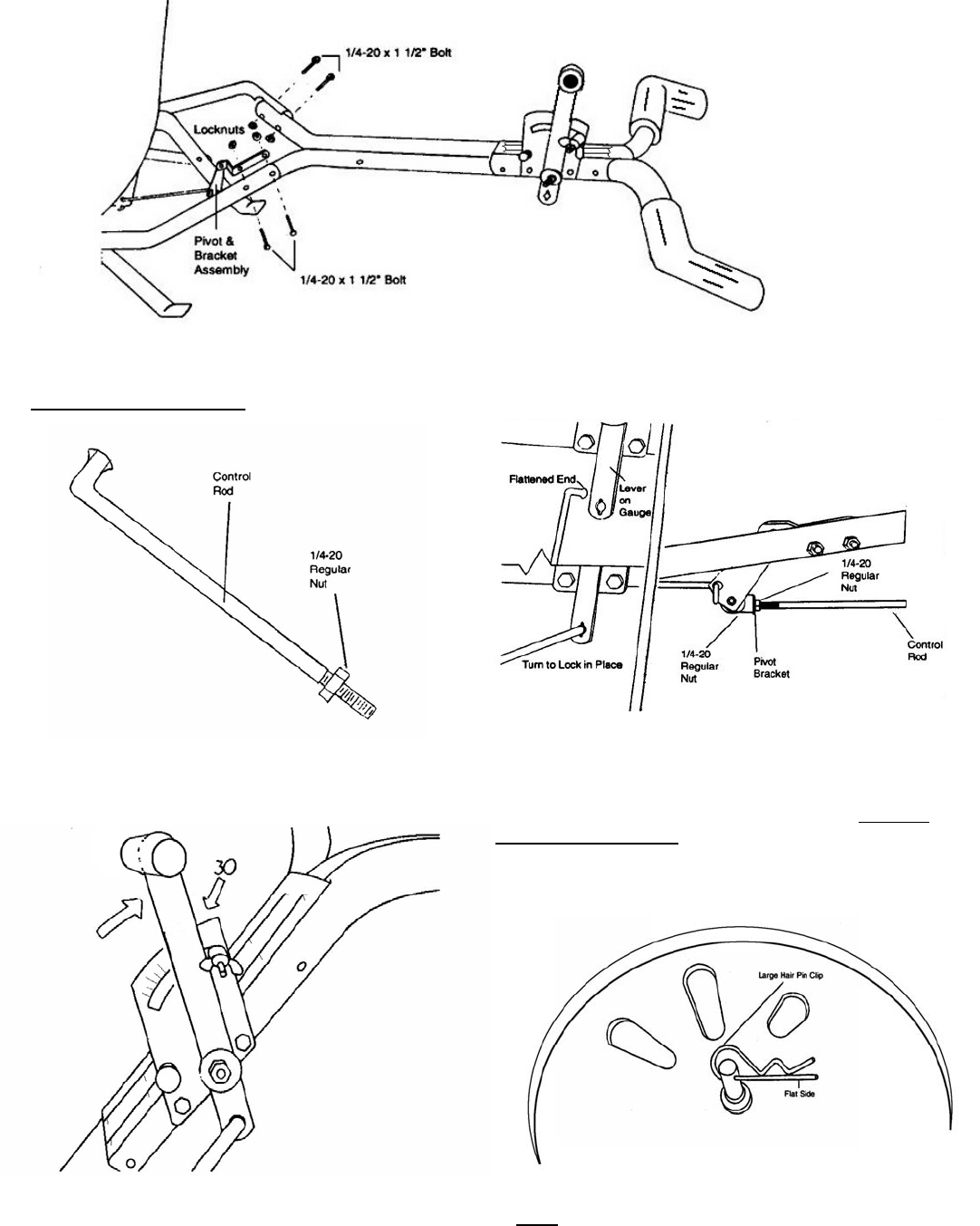
14. Pull lever back to setting “30” as shown. Next push pivot &
bracket forward so that the shut off plate in the hopper is in the full
open position. REMEMBER SETTING “30” ON THE FLOW
CONTROL LEVER MUST PLACE THE SHUT-OFF PLATE
IN THE FULL OPEN POSITION TO BE PROPERLY CALI-
BRATED. Now tighten the nuts against the pivot bracket to prevent
change in calibration.
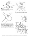
15. Insert large hair pin clip to pinion shaft on inside of hopper.
Note:
Position of flat side of hair pin clip. This pin should be in-
stalled as shown.
PAGE 4