


1-l DESCRIPTION
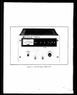
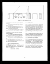
l-2 This instrument (Figure 1-l) is an all semi-
conductor high voltage supply suitable for either
bench or relay rack opwation.
It is a compact,
well-regulated, Constant Voltage/Current Limited
supply that will furnish 3, 000 volts et 6 m~lliampS
or carp be adjustEd throughout the output voltage
range, It is designed for *ppIicattons rwuiring
extreme EtabilIty, regulation, and insensitivity to
ambient temperature variations.
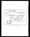
l-3 This supply utilizes a series regulated
“piggy-back” circuit technique.that consists of
placing e well-regulated low voltage power supply
in series with e lees well-regulated supply having
a greeter vo!tage capa.bility. The well-regulated
“piggy-back” supply continuously com!x”setee for
any ripple, load regulation, or Iine regulation de-
ficiencies of the main power source end adjusts
the voltage across its series regulator so that the
total output voltage remains constant despite dis-
turbances in the main voltage source.
l-4 OVERLOAD PROTECTION
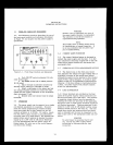
1-S The voltage thumbwheel witches select the
constant voltage level: an internal potentiometer
selecte the current limit level. The
supply
will
automatically crossover frbm conetant voltage to
currant limit operatim and vice versa if the output
current or voltage exceeds these
preset levels.
Detailed characteristics of the output current iim-
ittng are given in Paragraph 3-5.
l-6 The powor supply is protected from .+everse
voltage (positive voltage applied to negative ter-
minal) by en internal protection diode thet shunts
current across the output terminal6 when this con-
dition exists, clamping tha reveree voltage. Pro-
tection from rewrse current (current forced into
the power $upply in the direction oppoiite to the
output current) must be provided by prebading the
power supply (Paragraph 3-151, The power euppIy
cannot accept reverse current without damage.
l-7
COOLlNG
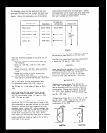
l-10 Output power is available vie ,mo WG-931/U
connectors mounted on the front panel of the sup-
ply,
Mating
cornwctors (UC=-932/U) are supplied
with the unit.
The output terminals are isolated
from the chassis and either the positive or the neg-
ative terminal tnay be connected to the chassis by
shorting the cer~ter ptn tQ the case of the epplica<
ble VG-931/U connector, or by grounding e wire
from the connector to the chassis,
The p0Wer
*UP-
ply is insulated to permit operation up to 1,000
volts dc off ground, i. e. the maximum potential
between either output terminal end ground shall not
exceed 4KVdc,
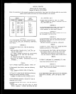
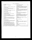
l-11 SPECIFICATIONS
l,-12 Detailed specificatlone for the
Pow” SUPPlY
are. given tn Table 1-l.
l-13 OPTIONS
l-14 Options are factory modifications of a stand-
ard instrument that are requested by the customer,
The following options are available for the instrum
mmt covered by this manual. Where necessary.
detaIled option information (operation, alignment,
etc.) is included throughout the manual,
Option No* Wescription
05
5OHz Inwt Modification, Factory
modification includes the substitution
of 60&z with SOHz magnetic
compo-
nent as indicated at the end of the
perte 1Ist in Section VI. In addition,
the overvoltage ProtectIon adjustment
is rechecked, refer to Section V.
18
23OVac +lO%, Sinqle-Phase
Xnput.
Factwy modiftcation includes the in-
stallation of a 230 volt
input trans-
former to replace the standard 115 volt
transformers es indicated at the reer
of the parts list in Section VI.
l-15 ACCESSORIES
l-16 The accessories listed in the following chart
may be
ordered wtth the power supply or SePeretel~
1-l