


TABLE
OF CONTENTS
section Page NQ.
I GENEML INFORMATION . . . .1-l
SeGtiOl7 Page No-
IV PRINCIPLES OF OPEPATION (ContWued)
l-l
l-4
l-7
l-9
l-11
l-13
I-15
l-17
l-20
Description
Overload ProtectIon
cooling
Output Terminals
Specifications
Ootions
A&essories
Instrument Identification
Ordering Additional Manuals
l-l
l-l
l-l
l-l
l-l
l-l
4-29 Protection Circuit
4-5
4-3 1 ovw Control Circuit
4-5
4-33 Reference Clrouit
4-5
4-37 M,e’cer Circuit
4-6
V MAINTENANCE.. . . . . . . . . . . , . . . ,.5-l
l-l 5-l
1-z
5-3
l-2
5-6
5-9
Introduction
5-l
High Voltage Precautions 5-l
Measurement Techniques
5-l
Test Equipment Required
5-l
P&ormanc~ Test
5-3
Rated Output, Meter, and Output
Controls Acouracy 5-3
Load Regulation
5-3
Line Regulation
5-4
Ripple and Noise
5-4
Ti-ansiwlt Recow?~ Tims
5-6
Output Impedance
5-7
Temperature Goefficient
5-a
Output StabMty
5-8
cument um1t
5-9
Troubleshooting
5-9
I I INSTALIATION . . .
Z.-l InitiaL 1nspemion
z-3
Mechanical Check
2-S Electrical Check
z-7 In~tellation Data
2-9 Location
Z-11 Rack Mounting
2-15 Input Power Requirwnents
Z-17 Power Cable
2-20 Repackaging for Shipment
I I r OPERATING INSTRUCTIONS.
3-, nlm-0” Cklcxk out Prooedure
3-3 opetat1otl
3-5 Currant Limit Provisions
3-7 Operation of Supply Beyond
Rated Output
3-9 Load Connection
3-13 output capacitance
3-15 Revwse Current Loading
3-17 Reverse voltage Loarang
IV PRINCrPLES OF OPERATION . . . . .
4-l
4-8
4-12
4-13
4-15
4-21
4-23
4-25
.2-l
Z-1
2-l
2-l
2-l
2-l
Z-l
2-2
2-2
2-z
.3-l
3-l
3-l
3-l
3-l
3-l
3-2
3-2
3-2
. . .
4-l
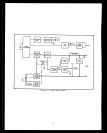
Overall Block Diagrem
Di~cusslon
Simplified Schematic Discussion
Detailed Glrcuit Analysis
Series Regulator
Constant Voltage Input Circuit
Driver and Error Amplifier
Current Limit Circuit
High Voltage Control and
Doubler Circuits
4-2
4-3
4-4
4-4
4-4
4-4
4-4
4-4
ii
5-11
5-14
S-17
s-13
5-z 1
s-35
5-39
5-42
5-46
5-49
5-51
r +?
a-32 Overall Troubleshooting
FYoceduw
s-9
5-59 Repair and Replacement S-15
5-61 Adjustment and Calibration 5-17
5-63 Output Voltage Zero and Tracking 5-17
S-65 Meter Mechanical Zero 5-17
5-67 Voltmeter Tmcking 5-17
5-63 Ammeter Zero S-17
5-71 Ammeter Ttacking 5-17
5-73 Overvoltage Protection 5-17
5-Y 5 Oven Control Circuit 5-18
5-77 Current Limit Adjustment
5-18
VI REPLACEAELE PARTS.. . . . . . . . . . , ,6-l
6-l lntroduotion 6-l
6-4 Ordering Information 6-l
Reference Designators
Abbreviations
Menufaoturers
6-8 Code List of Manufacturers 6-2
Parts List Table 6-5