


6 Hearth & Home Technologies • GFK-210-C Blower System Instructions 2201-938 Rev. E • 9/12
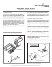
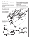
Figure 10. Remove Access Panel
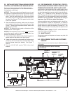
10.0 INSTALLING THE BLOWER (FireBrick Inserts)
For Models: ESCAPE-I30FB, ESCAPE-I35FB,
QFI30FB, QFI35FB
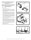
The factory installed brackets must be replaced with the
brackets included in the instruction bag before proceeding
with blower installation instructions below. See Figure 9.
For Models: ESCAPE-I30-C, ESCAPE-I35-C,
QFI30FB-C, QFI35FB-C
Proceed as follows:
1. Remove appliance from wall.
2. Disconnect power by shutting off circuit breaker or
unplugging appliance power cord from its receptacle.
3. Remove access panel from lower rear of the replace
insert. See Figure 10.
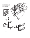
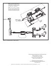
4. Connect white and green wires from blower wire as-
sembly to each blower. See Figure 12. Connect the
fuse wire assembly in series between black wires of
blower wire assembly and each blower. See Figure 12.
5. Route blower plug assembly through back of appliance
to right side of appliance. Ensure cable assembly is
routed in front of fan blade guard and through plastic
bushing on auxiliary mounting plate.
6. Insert plug from blower cable assembly into AUX300
receptacle. See Figure 12.
7. Position the right and left blower assembly into the rear
opening. Fasten each assembly with two sheetmetal
screws. Take care to ensure that blower housing or its
motor is clear of any adjacent metal. This will ensure
that no undue noise occurs during blower operation.
8. Bundle and zip tie loose wires to keep them from con-
tacting blower impeller blades
9. Reinstall access panel.
10. Reconnect power to the insert and install into wall.
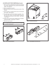
Figure 11. Attach Blower to Base
SCREWS
SCREWS
BRACKETS
(INCLUDED IN INSTRUCTION BAG)
Figure 9. Attach Brackets
BLOWER
ACCESS PANEL