


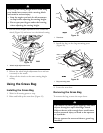
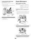
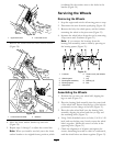
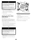
Figure 29
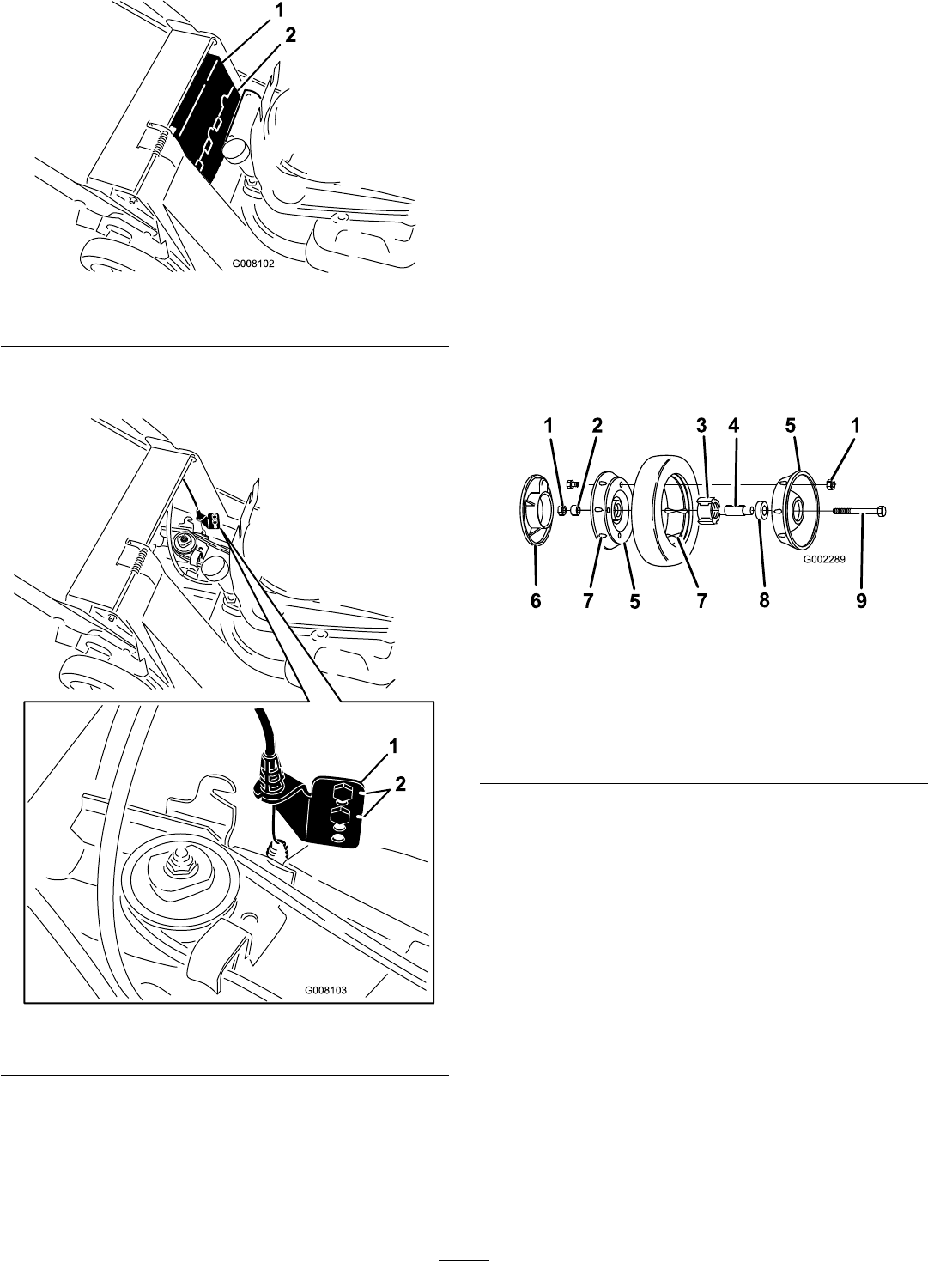
1. Upper belt cover 2. Lower belt cover
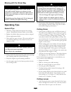
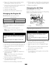
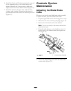
7. Remove the screws from the lower anchor bracket
(Figure 30).
Figure 30
1. Lower anchor bracket 2. Notches
8. Move the lower anchor bracket up one hole
(Figure 30).
9. Repeat steps 1 through 3 to adjust the control bar.
Note: When you install a new belt, move the lower
anchor bracket to its original factory position, which
is indicated by the notches next to the holes in the
bracket (Figure 30).
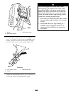
Servicing the Wheels
Removing the Wheels
1. Stop the engine and wait for all moving parts to stop.
2. Disconnect the wire from the spark plug (Figure 12).
3. Remove the bolt, the wheel spacer, and the locknut
mounting the wheel to the pivot arm (Figure 31).
4. Separate the wheel halves from the tyre by removing
4 cap screws and 4 locknuts (Figure 31).
Note: If you remove the bearings from the
bearing/hub assembly, remove them by pressing on
the bearing spacer (Figure 31).
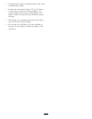
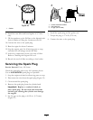
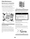
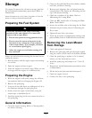
Figure 31
1. Locknuts
6. Plastic cover (rear wheels
only)
2. Wheel spacer 7. Lug
3. Bearing/hub assembly 8. Bearing (2)
4. Bearing spacer 9. Bolt
5. Wheel half
Assembling the Wheels
1. Position the tyre onto one wheel half, aligning the
lugs on each (Figure 31).
2. Place the bearing/hub assembly into the center hole
of the wheel half. Ensure that the legs of the hub are
positioned over the ange of the hole (Figure 31).
3. Place the other wheel half onto the bearing/hub
assembly, aligning the wheel and the tyre lugs and
the mounting holes (Figure 31).
4. Using 2 fully threaded screws or bolts (1/4-20 x 1.50
inch) and non-locking nuts, loosely secure the wheel
halves together. Mount the screws or bolts in the
opposing holes (Figure 31).
5. Check the alignment of all parts and tighten the
screws, alternating from side to side for a uniform t,
until the wheel halves are drawn together (Figure 31).
21