


GB
16
1740520
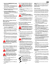
To Remove
1. Move the blade rotation control to the DIS-
ENGAGE position.
2. Move the shift lever to the neutral (N) posi-
tion.
3. Engage the parking brake.
4. Stop the engine.
5. Move the lift lever to the middle cutting posi-
tion.
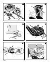
6. (Figure 15 and Figure 16) Disconnect the
rubber strap (1) from the latch pin (2) on
the connector tube (3).
7. (Figure 17) Hold the handles (4). Remove
the grass bag (5).
8. (Figure 18) Pull the connector tube (3)
through hole in rear plate (6).
9. Clean the connector tube (3) with soap and
water.
To Install
1. (Figure 16 and Figure 18) Slide the flange
(7) end of the connector tube (3) through
hole in rear plate (6).
2. (Figure 16) Slide the flange (7) end of the
connector tube (3) over the extension tube
(8).
3. (Figure 15 and Figure 16) Attach the
rubber strap (1) to the latch pin (2) on the
connector tube (3).
4. Install the grass bag.
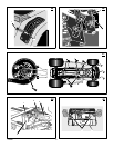
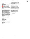
Inspect Blade (Figure 19)
WARNING: Before you inspect or
remove the blade, disconnect the
wire to the spark plug. If the blade
hits an object, stop the engine. Check the
unit for damage. The blade has sharp
edges. When you hold the blade, use
gloves or cloth material to protect your
hands.
If you keep the blade (1) sharp and inspect the
blade for damage, the blade will cut better and
be more safe to operate. Frequently check the
blade for excessive wear, cracks, or other
damage. Frequently check the nut (3) that holds
the blade (1). Keep the nut (3) tight. If the blade
hits an object, stop the engine. Disconnect the
wire to the s park plug. See if the blade is bent or
damaged. Check the blade adapter (5) for
damage. Before you operate the unit, replace
damaged parts with original equipment parts.
See the authorized service centre in your area.
Every three years, have an authorized service
person inspect the blade or replace the old
blade with an original equipment part.
How To Remove And Install The Blade
(Figure 19)
1. Remove the mower housing. See the instruc-
tions on “How To Remove The Mower Hous-
ing”.
2. Use a piece of wood to keep the blade from
rotating.
3. Remove the nut (3) that holds the blade (1).
4. To remove the blade (1) from the air assist
fan (8), remove fasteners (9) and (10).
5. Check the blade (1) and the blade adapter
(5) according to the instructions for “Inspect
Blade”. Check the air assist fan (8) for dam-
age. Replace badly worn or damaged parts
with original equipment parts. See an author-
ized service centre in your area.
6. Clean the top and bottom of the mower hous-
ing. Clean the air assist fan (8). Remove all
the grass and debris.
7. Assemble the blade (1) and air assist fan
(8) with fasteners (9) and (10). Tighten the
bolt (9) that holds the blade (1) to a torque
of 6,8 N--m (5 foot pounds).
8. Mount the blade (1) and blade adapter (5)
on the mandrel (6).
9. Mount the blade (1) so that the hi--lift edges
(7) are up. If the blade is upside down, the
blade will not cut correctly and can cause an
accident.
10.Fasten the blade (1) with the original
washers and nut (3). Make sure the outside
rim of the Belleville washer (2) is against
the blade (1).
WARNING: Always keep the nut (3)
tight that holds the blade (1). A
loose nut or blade can cause an
accident.
11.Tighten the nut (3) that holds the blade (1) to
a torque of 41,5 N--m (30 foot pounds) .
12.Install the mower housing. See “How To Re-
move The Mower Housing”.
How To Adjust The Blade Rotation
Control
WARNING: To prevent an injury, the
blade rotation control must operate
correctly.
In normal usage, the blade rotation control will
not require an adjustment. However, if the
cutting performance decreases or the quality of
cut is poor, make the following changes.
1. When you mow, make sure the throttle con-
trol in in the FAST position.
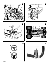
2. (Figure 20) Move the blade rotation control
to the DISENGAGE position (1).
3. Stop the engine. Disconnect the wire from
the spark plug.
4. Check the blade(s). Keep a sharp edge on
the blade(s). A blade that is not sharp will
cause the tips of the grass to become brown.
5. (Figure 21) Disconnect the blade drive
spring (2) from the blade control rod (1).
Move the blade drive spring (2) to the
middle hole (4). This will increase the tension
on the mower drive belt.
6. Attach the wire to the spark plug. Mow for a
short distance and again check the quality of
cut. If necessary, move the blade drive
spring (2) to the bottom hole (5)
7. Again check the quality of cut. If the quality of
cut has not improved, replace the mower
drive belt. See “How To Replace The Mower
Drive Belt”. If replacing the belt does not cor-
rect the problem, take the unit to an author-
ized service centre.
8. Move the blade rotation control to the DIS-
ENGAGE position. Stop the engine.
9. (Figure 22) Check the operation of the blade
brake. Rotate the mandrel pulley (5) with
your hand. Make sure the brake pad (7) is
pressed tightly against the mandrel pulley
(5).
WARNING: If the brake pad (7) does
not press tightly against the man-
drel pulley (5), take the unit to an
authorized service centre.
10.(Figure 20) Move the blade rotation control
to the ENGAGE position (2).
11. (Figure 22) Check the pad for the blade
brake (7). If the pad is excessively worn or
damaged, replace the brake pad assembly.
Correct replacement parts and assistance
are available from an authorized service
centre.
12.Attach the wire to the spark plug. Mow for a
short distance and again check the operation
of the blade rotation control.
13.When you move the blade rotation control to
the DISENGAGE position, all movement will
stop within five seconds. If there is move-
ment of the belt or the blade(s) continue to
rotate, engage and disengage the blade rota-
tion control five times to remove any excess
rubber from a new mower drive belt. If you
need assistance, take the unit to an author-
ized service centre.
14.(Figure 21) If you replace the mower drive
belt, move the blade drive spring (2) to the
top hole (3).
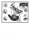
How To Adjust The Shift Lever
(Figure 30)
If the NEUTRAL position on the shift lever does
not match neutral on the gearbox, adjust the
shift lever as follows.
1. Stop the engine.
2. Disconnect the adjuster nut (2) from the
shifter bracket (3).
3. Make sure the shift lever is in the NEUTRAL
position.
4. Push the unit forward. Make sure the gear-
box is in neutral.
5. To align the adjuster nut (2) with the hole i n
the shifter bracket (3), turn the adjuster nut
(2).
6. Connect the adjuster nut (2) to the shifter
bracket (3).
7. Make sure the NEUTRAL position on the
shift lever matches neutral on the gearbox.
How To Check And Adjust The Clutch
(Figure 23)
If the motion drive belt is loose, the clutch will
slip when: going up a hill, pulling a heavy load,
or the unit will not move forward. Adjust the
clutch as follows.
WARNING: Before you make an in-
spection, adjustment, or repair to
the unit, disconnect the wire to the
spark plug. Remove the wire from the
spark plug to prevent the engine from
starting by accident.
1. Check the routing of the motion drive belt.
Make sure the belt is installed correctly and
is inside all the belt guides.
2. Remove the cotter pin (1), washer (2), and
brake spring (3) from the adjustable nut
(4).