


Page 6SKU 99623 For technical questions, please call 1-800-444-3353.
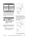
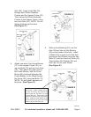
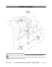
Insert the Handle Shaft (26) between 6.
the two Wheel Assembly Frames
(20). Attach the Pivot and Bracket
Assembly (19) to the Wheel Assem-
bly Frames and Handle Shaft, using
two Bolts (11) and two Nuts (21).
(See Figure F.)
FIGURE F
HANDLE SHAFT
(26)
WHEEL ASSY.
FRAME
(20)
NUT
(21)
BOLT
(11)
PIVOT
&
BRACKET
ASSY.
(19)
HOPPER
(16)
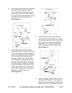
7. The Upper Handle (23) features
three positions for operating comfort.
To use the middle or upper positions,
place the Handle Spacer (1) between
the mounting holes nearest to the
Handle Covers (15). Insert a Bolt
(11) through the Upper Handle (23),
through the Handle Spacer, through
the other Upper Handle and secure
with a Flat Washer (48) and Nut (21).
Install the Gauge & Lever Assembly
(4) on the left hand side, using two
Bolts (11) and two Nuts (21).
(See Figure G.)
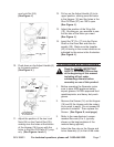
Unscrew and remove 8. one Lock Nut
(24) from the Control Rod (25). Insert
the threaded portion of the Control Rod
into the hole in the Pivot and Bracket
Assembly (19). Then re-thread the
Lock Nut back onto the Control Rod.
(See Figure H.)
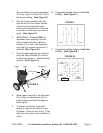
Insert the Adjust Connect Rod (46) into 9.
the Shut Off Plate (27). Then secure
the Adjust Connect Rod to the Shut Off
Plate, using one Flat Washer (48) and
FIGURE G
UPPER
HANDLE
(23)
FLAT WASHER (48)
HANDLE SPACER
(1)
NUTS (21)
BOLT
(11)
GAUGE
& LEVER
ASSY.
(4)
FIGURE H
LOCK
NUT
(24)
PIVOT & ASSY.
BRACKET
(19)
CONTROL ROD
(25)