Assembly - 48
ASSEMBLY
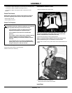
• Cut plastic tie straps fastening the front wheels to the shipping crate.
• Cut plastic tie straps holding the discharge chute up.
• Cut plastic tie straps securing the motion control levers to the
machine.
Check Fluid Levels
NOTE: Refer to the Service sections of the operator’s manual for
information regarding check locations and proper fluid levels.
• Check engine oil level.
• Check hydraulic oil level.
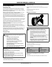
Check Tire Pressure
1.Check tires for damage.
2.Check tire pressure with an accurate gauge.
3.Add or remove air, if necessary.
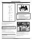
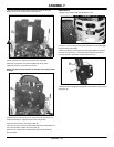
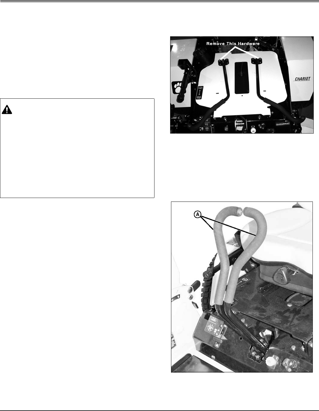
Install Motion Control Levers
1.Remove hardware from control arms.
NOTE: The control lever mounting brackets have six holes. The
levers can be installed in the top four holes, or for a lower lever
position, install the levers in the lower four holes.
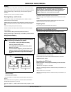
2. Raise the seat and prop it in the upright position.
NOTE: It is easiest during installation if the bottom rear bolts are
loosely installed first prior to installation of the front bolts.
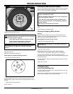
3. Align motion control levers (A) with control arms. Install hardware and
tighten.
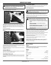
3.Check motion control lever alignment.
• Move both motion control levers forward.
Install Seat
CAUTION: Avoid injury! Explosive separation of tire and rim
parts is possible when they are serviced incorrectly:
•Do not attempt to mount a tire without the proper
equipment and experience to perform the job.
•Do not inflate the tires above the recommended
pressure.
•Do not weld or heat a wheel and tire assembly. Heat can
cause an increase in air pressure resulting in an
explosion. Welding can structurally weaken or deform
the wheel.
•Do not stand in front or over the tire assembly when
inflating. Use a clip-on chuck and extension hose long
enough to allow you to stand to one side.


