


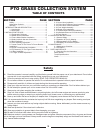
5
SECTION I
INTRODUCTION AND DESCRIPTION
1-1 Introduction
1-2 Description
We are pleased to have you as a PECO customer. Your
collection system has been designed to give you a low
maintenance, simple, and effective way to collect the
grass clippings from your mower. This manual is
provided to give you the necessary instructions to
properly mount and operate the collection system on
your mower. Please read this manual thoroughly.
Understand what each control is for and how to use it.
Observe all safety decal precautions on the machine and
noted throughout the manual.
All references made to right, left, front, rear, top
or bottom are as viewed from the normal operator’s
position on the mower.
The collection system is designed for turf maintenance
where there is a need to collect the grass clippings as
the mower cuts the turf. It is also good for picking up
leaves and twigs in pre-season and post-season clean-
up.
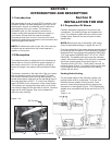
The blower, mounted on the right side of the unit, uses a
belt and gearbox system from the engine PTO shaft.
Drive train protection comes through belt slippage. The
blower draws grass clippings from the discharge area of
the cutter deck back to the 3 - 3.3 cubic foot collection
bags P#(G0002) at the rear portion of the mower frame.
The operator can engage the blower with a push of the
over-center linkage on the right side of the unit. Once the
bags are full with clippings, they can be released to
make for easy dumping.
NOTE:
Section II
INSTALLATION FOR USE
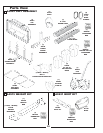
2-1 Preparation Of Mower
Carefully dismantle shipping box from around the
components. Cut retaining straps and separate the
parts. The collection system will have various parts
located inside. Remove and sort all parts for easy
identification.
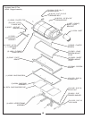
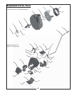
Before each step of assembly it will help to
study the exploded drawings on pages 8,9 and 10.
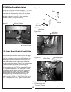
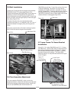
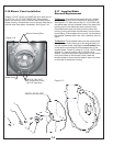
From the underside of the mower engine remove the bolt
and bushing from the electric clutch assembly. Replace
these parts with the engine pulley assembly ,
7/16” lock washer P#(K0053) and 7/16”-20 x 4” HHCS
P#(K0359). The added pulley will power the collection
system. Note that the center of the hub that is extended
should be upward toward the engine .
Torque the bolt to 55 ft./lbs. Once pulley is secure, tie
hydraulic hoses (Figure 1-1a) away from the pulley with
(2) provided zip ties to prevent pulley from making
contact with the hose.
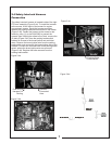
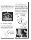
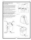
For the added weight of the collection system, the
parking brake must be re-adjusted. To do this, first
Remove the rear wheels from the mower. Once
removed, reset the spring and the stop gap per the
dimensions in the diagram (Figure 1-1b). Replace the
wheels when completed and torque each bolt to 51-72
ft./lbs.
NOTE:
Parking Brake Setting
P#(A0419)
(Figure 1-1a)
Figure 1-1a.
Figure 1-1b.
1.432”
0.0” to 0.0625
Zip Tie Hose
Engine Pulley
7/16”-20 x 4” HHCS