


12
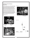
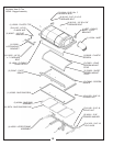
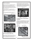
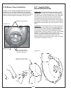
2-10 Boot Installation
First, remove the deflector shield by pulling out the
locking pin and lifting the shield out of deck mount tube.
To install the boot to the mower deck, attach the boot
plate mount pin P#(B0274) to the boot plate P#(B0285)
using (1) 3/8”-16 x 3/4” HHCS P#(K1190) and (1) 3/8”-16
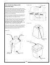
lock washer P#(K0048) See figure 2-10a. Next, loosely
fasten the boot P#(E1125) to boot plate using (2) 3/8”-16
x 1” carriage bolts P#(K1182) and (2) 3/8”-16 flange nuts
(P#K1215) with the head of the bolts placed from the
inside of the boot. Insert the boot plate mount pin into
the deck mount tube and slide the slot of the boot plate
over the tab at the top of the discharge opening. Place
the deflector shield in the transport position on top of the
boot plate. Replace the locking pin. Adjust the boot to fit
securely against the discharge opening and tighten the
(2) 3/8”-16 flange nuts. See figure 2-10b for clarity.
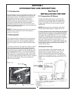
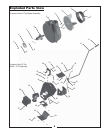
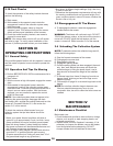
2-8 Upper Frame Assembly
Installation
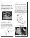
2-9 Top Assembly To The Upper
Frame Assembly Installation
NOTE: During this step, it is suggested that two
people install the top frame to the lower frame.
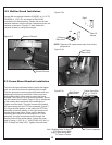
Using two people to raise the top frame, lift the top frame
above the lower frame making sure the bag frames are
located away from the engine as shown in Figure 2-8.
Slide the top frame vertical tube into the lower Frame
vertical tube aligning the holes. Insert (1) ½” x 2-1/2”
clevis pin P#(K0133) through the holes and fasten with
(1) 5/32” x 2-5/8” hair pin clip P#(K0088).
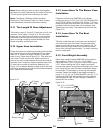
Align the pivot brackets of the top assembly P#(A0551)
to the pivot point on either side of the upper frame
assembly. Place (1) P#(K0041) fender washer between
each pivot point (Figure 2-9) and fasten each side by
using (1) P#(K1153) 5/16”-18 x 3/4” HHCS and (1)
P#(K1180) 5/16”-18 nyloc nut. When fastening leave nut
slightly loose so that the top can pivot freely.
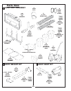
Lower Frame
½” x 2-1/2” Clevis Pin
5/32” x 2-5/8”
Hair Pin Clip
Top Frame
Figure 2-8.
Figure 2-9.
Top Assembly Here
Fasten Here With
5/16” x 3/4” HHCS
5/16” Nyloc Nut
Fender Washer
Boot Plate
Mount Pin
Boot
Plate
(1) 3/8” Lock Washer
(1) 3/8”-16 x 3/8” HHCS
Boot
(2) 3/8”-16 x 1” Carriage Bolts
(2) 3/8” Flange Nuts
Figure 2-10b.
Locking
Pin
Figure 2-10a.
Exhaust Deflector
in Transport Position
Tab
Boot
Plate