


GB - 22
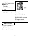
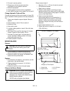
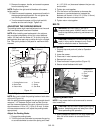
2. Remove the spacer, handle, and eccentric spacers
from the steering lever.
NOTE: Position the right and left handles at the same
height position.
3. Install the eccentric spacers, spacers and handle in
the appropriate height position. Do not tighten the
nuts holding the eccentric spacers.
4. Turn the eccentric spacer until the right and left
handles are the same height. Tighten nut.
ADJUSTING THE PARKING BRAKE
The parking brake might need adjustment over time and
after new brake pads have been installed.
NOTE: After installing new brake pads in the calipers,
they must be burnished by driving for a short distance
(about 100 feet) with the brake on. To do this, bring the
parking brake lever part-way up while driving in a straight
line. This quickly breaks-in the pads for maximum effec-
tiveness.
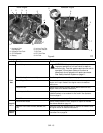
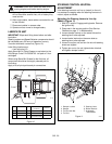
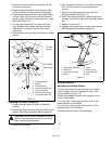
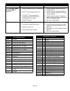
Check Adjustment
NOTE: Be sure to check the parking brake on both sides
of the unit (Figure 14).
With the parking brake engaged, the spring length should
measure 1 1/2" between the jam nuts and the trunnion
and the clearance between the return nuts and trunnion
should measure 1/16 to 1/8" (1.59 to 3.18 mm). If either
of these measurements is off, adjust the parking brake
appropriately.
Adjust the Parking Brake
1. Engage the parking brake.
2. Turn the jam nuts clockwise to compress the spring
or counterclockwise to extend the spring until there
is 1-1/2" (3.81 cm) clearance between the jam nuts
and trunnion.
3. Tighten jam nuts together.
4. Turn the return nuts clockwise to decrease the
distance or counterclockwise to increase the
distance until there is 1/16 to 1/8" (1.59 to 3.18 mm)
between the return nuts and trunnion.
5. Tighten return nuts together.
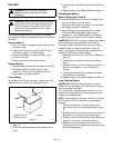
BELTS
Belt Access
1. Properly stop and park unit (refer to Operation
Section).
2. Lower the mower.
3. Place seat in most rearward position.
4. Remove belt covers.
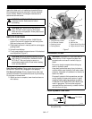
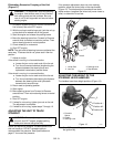
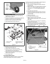
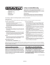
5. Place foot board in open position (Figure 15).
6. Secure raised footboard with latch.
Replacing Mower Belts
NOTE: Long mower belt must be removed to remove
short mower belt.
1. Slowly release the tension on the long mower belt
idler until all the tension is removed from the
springs.
1. Parking Brake Lever
2. Brake Rod
3. Return Nuts
4. Trunnion
5. Spring
6. Jam Nuts
Figure 14
OF3303
1-1/2"
(3.81 cm)
1/16 to 1/8" (1.59
to 3.18 mm)
12
3
4
5
6
2
WARNING: MOVING PARTS can cut or
amputate body parts. ALWAYS wait for moving
parts to stop before performing maintenance or
service.
CAUTION: DAMAGED OR WORN BELTS may
result in injury and/or damage to unit. Check
belts for excessive wear or cracks often.
CAUTION: Use care when releasing idler spring
tension. Keep body parts well away from idlers
when performing this operation.
Figure 15
1
3
2
1. Footboard in
open position
2. Pivot
3. Support
Frame
4. Latch
OF3580
4