


GB - 21
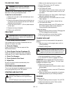
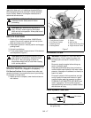
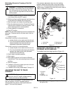
Eliminating Excessive Creeping of the Unit
(Figure 11)
1. If hydraulic system is cold, run unit for a minimum of
five minutes, then shut OFF engine.
2. With the unit up to and facing a wall, jack the unit up
so that both drive wheels are off the ground.
3. Start the engine and release the parking brake.
4. Move the steering levers from Forward to Reverse
several times to make sure controls are free. Then
return steering levers to neutral position.
5. Check wheel(s) for movement.
6. Shut OFF engine.
NOTE: The right and left steering levers are adjusted the
same way. To access the tie-rod, place seat in service
position.
7. Adjust tie-rod(s):
If the wheel is moving in a forward direction:
a. Loosen the jam nut on each end of the tie-rod.
b. Turn tie-rod counterclockwise (lengthening the
distance between the steering lever and
hydrostatic transmission) several times.
If the wheel is moving in a reverse direction:
a. Loosen the jam nut on each end of the tie-rod.
b. Turn tie-rod clockwise (decreasing the distance
between the steering lever and hydrostatic
transmission) several times.
8. Return seat to operating position.
9. Start engine.
10. Move steering levers from Forward to Reverse
several times. Then return steering levers to neutral
position.
11. Shut OFF engine.
12. If wheel is not moving, tighten jam nuts on tie-rod.
The adjustment is complete.
13. If wheel is still moving, repeat steps 7 through 12.
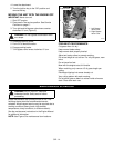
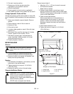
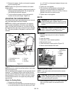
ADJUSTING THE UNIT TO TRACK
STRAIGHT
Check and adjust tire pressure. Increase pressure on
side unit tracks to. DO NOT exceed maximum
recommended tire pressure. See Specifications on
page 27 for correct tire pressure.
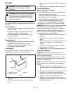
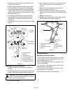
If tire pressure adjustment does not solve tracking
problem, adjust the limiter bolts on the stop bracket
(Figure 12). Front bolts adjust forward and rear bolts
adjust reverse. Lengthen the limiter bolt (move closer to
lever) on side which is too fast.
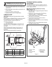
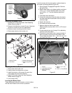
ADJUSTING THE HEIGHT OF THE
STEERING LEVER HANDLES
The handles have three height positions (Figure 13).
1. Shut OFF engine. Engage parking brake. Remove
the ignition key.
WARNING: This adjustment requires operating
the engine. Use extreme care to avoid contact
with moving parts and hot surfaces. Be sure
rear of unit is well supported and secure before
starting engine.
WARNING: Prior to adjusting the tracking of
the unit, shut OFF engine, engage parking
brake, and remove the ignition key.
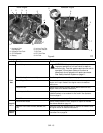
Figure 12
1. Limiter Bolt
2. Jam Nut
3. Steering Lever
4. Stop Bracket
OF3577
1
2
3
1
4
2
Figure 13
OF3570
Position # 1
Position # 2
Position # 3
3
1
2
1. Eccentric
Spacer
2. Handle
3. Steering Lever