


GB - 23
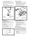
4. Measure from bottom of mower blade end to
ground.
5. Set hydraulic lift cylinder so cut of height reads the
same as blade height measurement.
6. Loosen the locknuts on the side where the chains
are slack and slide the bolt down the slot until the
chain is tight.
7. Tighten bolt and nuts in mower mounting brackets.
8. Lift mower and remove blocks.
9. Measure height of deck at each side.
Measurements must be within 1/16" (1.59 mm) of
each other.
10. If measurements are out of range, fix by adjusting
chains on low side of deck.
11. Once deck is level side to side, measure height of
deck at middle of front and on both sides of rear.
Front of deck should be 1/8" (3.18 mm) lower than
rear.
12. To adjust, loosen rear hex nut of the front mower lift
pivot on each rod.
13. Turn the front hex nut on each rod until mower is
1/8" (3.18 mm) lower in front.
NOTE: If mower cannot be leveled it may be necessary
to loosen the rear nut of the rear mower lift pivot to get
more threads at the front of rod for adjustment. After loos-
ening rear nut and adjusting level, tighten front nut on
rear mower lift pivot.
14. Tighten rear hex nut on each rod that was loosened
in step 12.
SHORT TERM
NEVER spray unit with high pressure water or store unit
outdoors.
Inspect unit for visible signs of wear, breakage or
damage.
Keep all nuts, bolts and screws properly tightened and
know unit is in safe working condition.
Store unit in a cool, dry protected area.
LONG TERM
Clean unit thoroughly with mild soap and low pressure
water and lubricate (See Lubricate Unit on page 18 in
Maintenance). Touch up all scratched painted surfaces.
Remove weight from wheels by putting blocks under
frame or axle.
When storing unit for extended periods of time, remove
all fuel from tank and carburetor (run dry). Refer to
Engine Manual.
Clean and charge the battery. Charge battery every three
to four weeks when storing unit.
To Take the Unit Out of Storage
1. Refer to the engine service manual to prepare the
engine for service.
2. Put fresh, clean fuel in the fuel tank.
3. Begin the maintenance schedule.
4. Charge and install the battery.
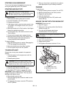
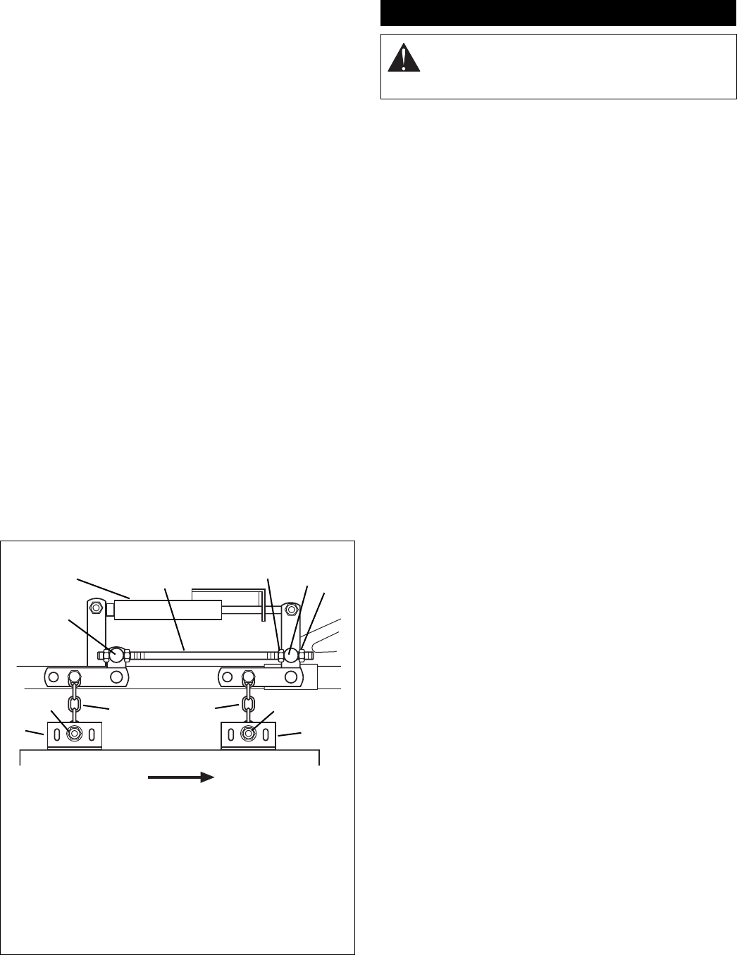
OF3340
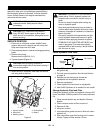
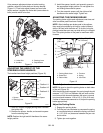
Front of Unit
1. Rod
2. Rear Hex Nut
3. Front Hex Nut
4. Chains
5. Lock Nuts and Slots
6. Mower Mounting
Brackets
7. Front Mower Lift Pivot
8. Rear Mower Lift Pivot
9. Hydraulic Cylinder
Right Side View
Figure 19
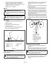
NOTE: ALWAYS replace link chains in same holes
they were removed from. Link chain mounting posi-
tions vary by deck size.
1
2
7
3
6
5
4
4
5
6
8
9
STORAGE
WARNING: AVOID INJURY. Read and
understand entire Safety section before
proceeding.