


GB - 20
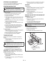
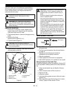
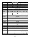
If tire pressure adjustment does not solve tracking
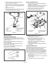
problem, adjust the limiter bolts on the stop bracket
(Figure 11). Front bolts adjust forward and rear bolts
adjust reverse. Lengthen the limiter bolt (move closer to
lever) on side which is too fast.
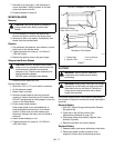
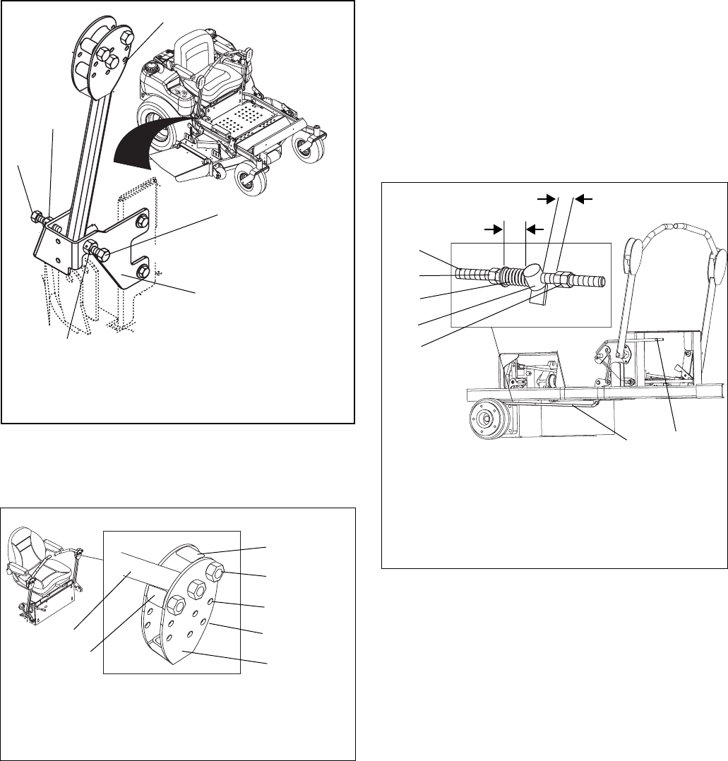
ADJUSTING THE HEIGHT OF THE
STEERING LEVER HANDLES
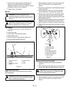
The handles have three height positions (Figure 12).
1. Shut OFF engine. Engage parking brake. Remove
the ignition key.
2. Remove the spacer, handle, and eccentric spacer
from the steering lever.
NOTE: Position the right and left handles at the same
height position.
3. Install the spacer, handle, and eccentric spacer in
the appropriate height position. Do not tighten the
nut holding the eccentric spacer.
4. Turn the eccentric spacer until the right and left
handles are the same height. Tighten nut.
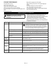
ADJUSTING THE PARKING BRAKE
The parking brake might need adjustment over time and
after new brake pads have been installed.
NOTE: After installing new brake pads in the calipers,
they must be burnished by driving for a short distance
(about 100 feet) with the brake on. To do this, bring the
parking brake lever part-way up while driving in a straight
line. This quickly breaks-in the pads for maximum effec-
tiveness
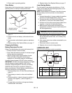
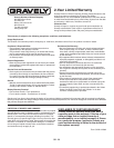
Check Adjustment
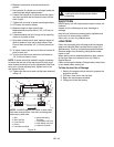
NOTE: Be sure to check the parking brake on both sides
of the unit (Figure 13).
With the parking brake engaged, the spring length should
measure 1 1/2" (3.81 cm) between the jam nuts and the
trunnion and the clearance between the return nuts and
trunnion should measure 1/16 to 1/8" (1.59 to 3.18 mm).
If either of these measurements is off, adjust the parking
brake appropriately.
Adjust the Parking Brake
1. Engage the parking brake.
2. Turn the jam nuts clockwise to compress the spring
or counterclockwise to extend the spring until there
is 1-1/2" (3.81 cm) clearance between the jam nuts
and trunnion.
3. Tighten jam nuts together.
Figure 11
1. Limiter Bolt
2. Jam Nut
3. Steering Lever
4. Stop Bracket
OF3572
1
2
3
1
4
2
Figure 12
OF3304
Position # 1
Position # 2
Position # 3
1. Spacer
2. Steering Lever
3. Eccentric Spacer
4. Handle
1
2
3
4
1. Parking Brake Lever
2. Brake Rod
3. Return Nuts
4. Trunnion
5. Spring
6. Jam Nuts
Figure 13
OF3303
1-1/2"
(3.81 cm)
1/16 to 1/8" (1.59
to 3.18 mm)
12
3
4
5
6
2