7
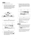
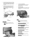
6. BLADE INSTALLATION: Place the blade and
collars on the shaft at the desired cutting height.
Put the flat washer and nut on as in
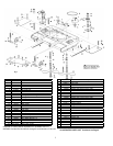
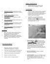
7. BELT REMOVAL: Remove the belt covers.
Unhook one end of each spring; use a spring
puller or clamp-lock pliers. Remove the drive.
Remove the belts. See figs 2, 3, & 4. fig 1, Item
14 and 15. Hold the rotor shaft with a 3/8" socket
drive and torque the nut to 100 ft. lbs. Similar
tightness can be reached with a Gravely
11367E1 Wrench or any 16" length handle
wrench when used by an average man, fig 9.
8. BELT INSTALLATION: See ASSEMBLY
paragraphs 4, 6, 7, 8, and 9 .
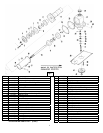
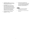
9. Safety clutch action is regulated by the
attachment clutch assembly, fig 5, Items 1, 3, 4,
5, 6, 7 and 8. Loosen all 6 nuts, Items 8. Tighten
the 6 bolts all the way into the threaded back
plate, Items 1 & 7. Back off each bolt 1/2 turn.
Lock the bolts in position with the nuts
STORAGE
1. Perform all that applies from ROUTINE
MAINTENANCE and LUBRICATION.
2. Apply a light coat of oil to preserve finish and
appearance.


