


SERVICE
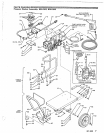
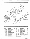
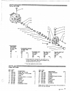
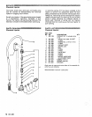
Pump
(Refer to Parts Drawing, Page 11)
MOTE:
Three sizes of metric wrenches are
M17, and M6 Allen wrench.
necessary for servicing the. pump; M30,
Valves:
1.
Remove the hex plug
(5)
from manifold (6) using
M30 wrench.
2.
Examineo-ring(4)underplugandreplace'ifcutsor
distortion exist.
'3.
Remove valve~unit and O-ring (3) from cavity.
NOTE:
Valve
unit
may come apart during
removal.
4. Replace valve unit
with
P/.N 801-472.
7. Install retaining screw assembly into plunger and
torque to 14.4
ft.
Ibs. (2 K/m).
8. Lubricate each plunger and carefully slide
manifold onto crankcase.
9.
Replace the six capscrews and snug them up.
Torque to
16
ft. Ibs. (2.2 K/m).
NOTE:
The six capscrews must be torqued
evenly to apply equal pressure on the
doesn't bind or jam. This
is
best done by
manifold
so
that
it
seats properly and
torquing bolts closest to the center of the
manifold first and then working out from
those bolts,
5. Replace hex plug and torque to 72.3
ft.
Ibs.
(10
'Servicing V-Packings:
K/m).
NOTE:
Use packing repair
kit
P/N 801 -662.
NOTE:
Hex plug should be re-torqued after
5
1. After removing thesixcapscrewsandthe manifold
hours operation. carefully pull packing retainer (12) from the
manifold. Examine O-ring (13) and replace if
necessary. Pumping Section:
1.
Remove the six Allen head cap screws (1)from the
manifold using the M6 Allen wrench.
2.
Remove
low
pressure packing
(10)
and head ring
2. Carefully separate the manifold from the
crankcase.
NOTE:
It
may be necessary to tap manifold
lightly
with
mallet to loosen.
CAUTION
plungers when removing to avoid damage to
Keep manifold properly aligned
with
ceramic
plungers or seals.
3. Carefully examine each plunger
(19)
for any
scoring and replace if necessary,
Servicing Plungers:
1.
Loosen plunger retainiw screw (15) 5-6 turns,
crankcase. This
will
separate plunger and
using "17 wrench. Push plunger towards
retaining screw.
2. Remove retaining screw from plunger and
bearinglgasket washer
(1
6). Replace
if
necessary
examine O-ring
(1
7). back-up ring
(1
8), and copper
using plunger repair kit P/N'801-474.
3. Remove plunger from plunger rod and remove
copper flinger
(20).
Clean or replace if necessary.
4.
Lightly grease flinger and replace
it
on plunger rod.
5. Replace plunger.
6.
Lightly grease retaining screw assembly to avoid
cutting O-ring. Lightlygrease outer endof plunger.
3. Pull intermediate retainer ring
(1
1)from manifold,
high pressure packing
(10)
and head ring
(9).
4. Inspect all parts and replace if necessary
NOTE:
If just the packings are needed use kit
801-662.
If
rings or retainers need
replacement use kit 801 -664.
5.
Thoroughly clean packing cavity
in
manifold and
examine. Lightly grease packing cavity.
6. Replace packing assembly
in
the following order:
head ring
(9).
packing
(10).
intermediate ring
(1
1).
and O-ring (13).
head ring
(9).
packing
(10).
packing retainer (12).
CAUTION
Carefully study the location
of
each part and the
position of the seals to assure proper
reassembly and operation.
7.
Lubricate each plunger and carefully slide
manifold onto crankcase.
NOTE:
When replacing the manifold onto
exercised to avoid damage
to
the seals.
plungers, extreme caution should be
8.
Replace the six capscrews
in
the manifold and
tighten as previously described (step
9
under
servicing plungers).
.
..
,.
.,.
..
. ..
..
10
801-888