


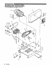
PUMP
SERVICE
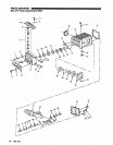
Servicing the Plungers
To
reduce the risk
of
serious bodily injury, NOTE Plunger repair kit, P/N
803-677
is available
to
including fluid injection, splashing in the eyes or replace retainers, O-rings. washers and
follow the Pressure Relief Procedure
Warnlng
on the skin, or injury from moving parts, always backup rings for three cylinders.
before proceeding.
-
NOTE The following metric wrenches are needed:
M10, M13 and M30. Repair kits are available.
Refer
to
the individual repair sections and the
results, use
all parts in the kits.
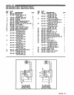
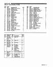
pump parts
page for more details. For the best
NOTE: There are
Wo different
tool
kits to aid
in
servicing the pump. P/N
800-298
is used to
ease installation
of
packings. P/N
800-271
includes the items in
800-298
and
tools
to
aid
in the removal of packing retainers.
Valves
NOTE: For a
set
of six valves, order P/N
803-664
or
803-666.
1.
Loosen the plunger retaining screw five
to
six tums,
using
an
MlOwrench. Push the plungertowards the
crankcase
to
separate the plunger and retaining
screw.
2.
Remove the screw from ihe plunger and examine
washer. Replace these parts,
if
necessary, using kit
the O-ring, backup ring and copper bearing/gasket
3. Remove the plunger and flinger from the plunger
shaft. Clean, examine and replace parts as
necessary.
801-474.
4.
Inspect the plunger shaft for oil leakage from the
crankcase.
If
leaking is obvious, replace the oil
seals. Otherwise,
DO
NOT remove these seals
as
they cannot be reused. An oil seal kit is available
to
replace the seals.
1.
2.
3.
4.
Remove
the
hex
plug from
the
manifold
using
an
5.
Lightly grease the oil seal,
if
it
is being replaced,
M30 wrench.
and the flinger and replace them on the plunger
Examine the O-ring under the hex plug and replace
shaft. Then install the plunger.
it
if
it is cut or distorted.
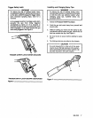
6.
Lightly grease the retaining screw and the outer end
Remove the valve assembly from the cavity; the
assembly may come apart.
oiihephger. Place the wisher, O-ring and backup
the plunger. Torque
to
14.4
ft-lb
(19.5
Nm).
ring around the screw and install the screw through
NOTE: Retorque the plug after
5
hours of operation.
Pumping Section
1.
Remove the eight capscrews and lockwashers from
the manifold using an M13 wrench.
2.
Carefully separate the manifold from the crankcase.
NOTE:
It
may be necessary to tap the manifold lightly
with a
soft
mallet to loosen.
CAUTION
Keep the manifold properly aligned with the
damage
to
the plunger or seals.
ceramic plungers when removing to avoid
3. Carefully examine each plunger for any scoring or
cracking and replace as necessary.
7.
Lubricate. the outside of each plunger. Slide the
manifold onto the crankcase, being careful not
to
damage the seals.
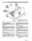
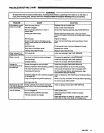
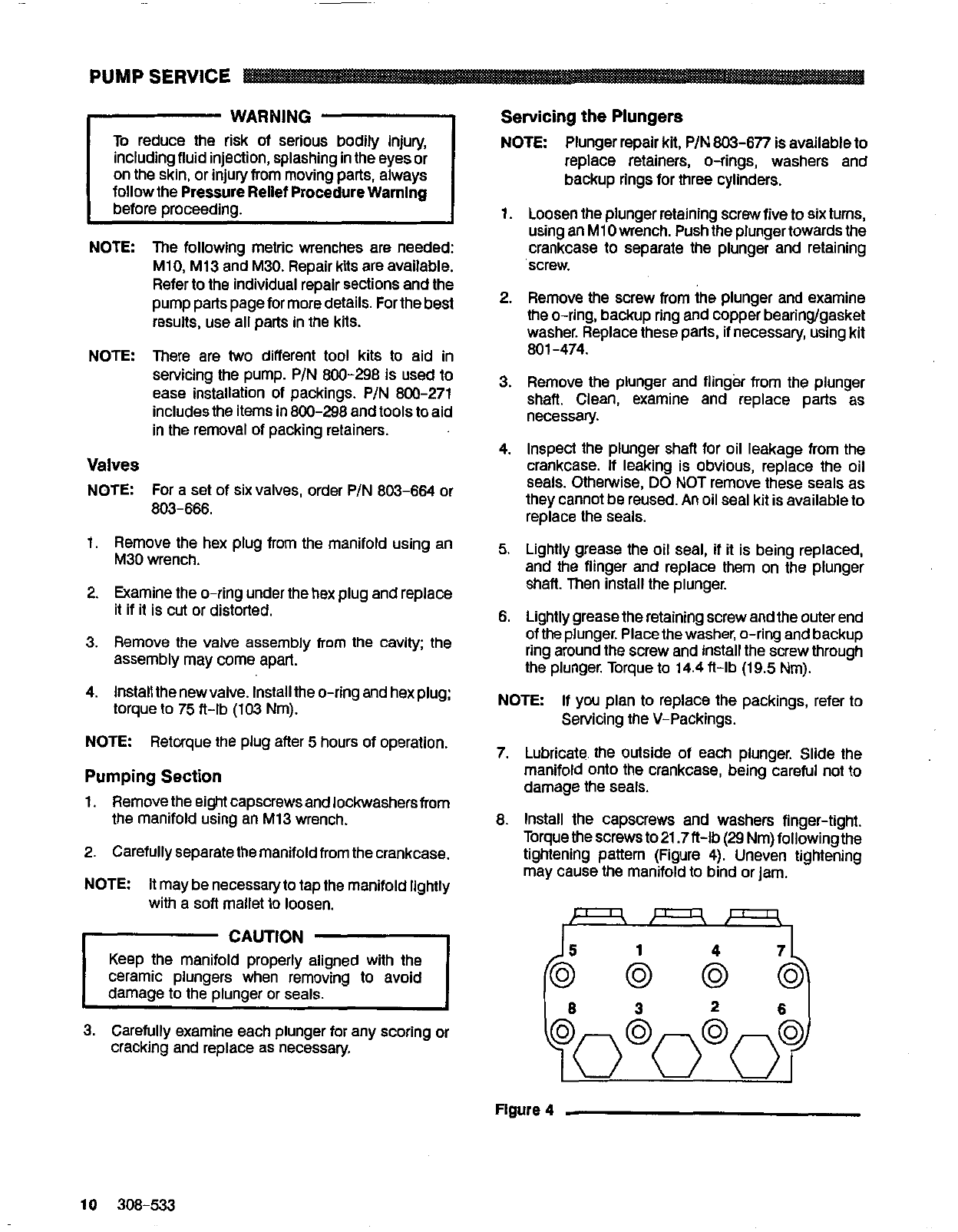
8.
Install the capscrews and washers finger-tight.
tightening pattern (Figure
4).
Uneven tightening
Torquethescrewsto21.7ft-lb(29Nm)followingthe
may cause the manifold
to
bind or jam.
I
Figure
4
10
308-533