


-
Accompanied
By
Smooth
Decreased Delivery
Operation
Excessive Leakage
suction piping (suction valve
Plugged or constricted
not fully open);
Collapsed suction hose.
Worn valve seats.
Slipping couplers.
Worn piston cups;
Loose
piston bolts;
Damaged O-rings;
Cracked ceramic liners;
Faulty gaskets;
Loose
valve caps;
Loose cylinder head bolts or
malfitted heads.
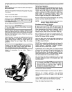
Examine the water
in
the barrel or tank for air
bubbles while the pump is discharging. If no
bubbles are seen and the discharge has actually
decreased, look for plug-ups, worn valve seats, or
collapsed suction hose. If bubbles are seen, look
for air leaks in the suction piping or for air leaking
past the piston cups. These leaks are hard to find
because they are leaking "in" rather than
"out".
However, if arrangements are made to put
pressure into the suction
piping
or if new cups
smooth out the pump operation, the problem is
solved
Look for worn or pitted valve seats. Replace if
necessary.
eccentric roller bearing and yoke pads with a
Measure clearance between outer surface or
feeler gauge. This should not exceed
0.010
inch
(0.2%
mm).
NOTE:
Worn yoke pads will give
a
very noisy
operation. Replace the yoke or pads if
necessary.
cup
will
not leak severely until
it
is torn. The piston
Examine pistons and cups for wear. Generally a
should not be more than
0.020
in.
10.508
mm)
out
of round.
Tighten
loose
piston bolts, cylinder head bolts and
80-grit sandpaper which is laid on
a
flat surface.
valve caps. Remove head and sand flat part on
Check O-rings and gaskets for wear or breaks.
ceramic liners for cracks. Replace all damaged
Remove cylinder heads and blocks to examine
parts.
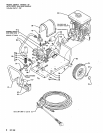
SERVICE
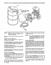
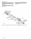
Pistons and Yoke
Take
off
the cylinder head
(14)
by removing four 112 in.
Assembleall piston parts (10. 11.
12.
13, 21,
22,
23,
24)
'
'
as shown and push the assembly into the. cylinder liner.
socket head capscrews (A).
See
Fig 3. Make sure that the O-ring is
in
the recess of the piston
cap.
(13) from the yoke. Slide out the cylinder liner
(21)
and
Use
a
7/32 in. socket wrench to unscrew the piston bolt
Screw the piston bolt into the yoke.
The
bolt has
a
piston assembly. Leave
the
yoke
in
place.
will require a-little extra effort to turn. Make certain
it
is
countersunk head capscrew of the lockwell type and
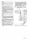
Examine the ceramic cylinder liner (21) for cracks. tight to prevent leakage through the b.olt hole.
Replace worn or cracked parts before reassembling into
pump body.
NOTE:
Dirty grease sludge adhering
to
the wall of
the cylinder liner should be removed with
emery cloth before the liner is replaced in the
pump body.
Repeat the procedure for the opposite side
of
the pump.
307-308 5