


2. Slide the auxiliary handle over the housing as per the
attached diagram, ensuring the handle is orientated so
as the serrated or pattern surface aligns with the same
pattern surface on the housing.
3. Fit the auxiliary locking knob and bolt through the
handle and housing from the left hand side of the
blower vac (same side as the blower vacuum selector)
and tighten in a clockwise direction.
4. To adjust the angle of the handle, loosen the auxiliary
locking knob (rotate in an anti-clockwise direction) and
move the handle to the preferred position and then
tighten the knob firmly.
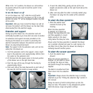
Shoulder strap
Your ST1800 blower vac is supplied with a shoulder strap
to assist with user comfort during use. The strap assembly
can be fitted or removed from the top of the housing via
the metal buckle on the end of the strap.
1. To open the buckle, remove the small retaining screw
and washer, which retains the buckle pin in position.
After removing the small screw & washer, remove the
larger pin from the buckle. If the buckle was on the
hosing, by removing the pin, the buckle will be free of
the housing.
2. If you are fitting the buckle to the housing, slide
the pin through the one side of the buckle and then
through the housing. On the other side of the housing
allow the pin to again pass through the hole in the
buckle. Fit the small washer on to the retaining screw,
and fit the screw into the end of the pin and tighten
firmly.
3. To adjust the length of the shoulder strap, slide the
plastic adjusting buckle up or down the strap,
A quick release is also fitted to the strap which allows the
strap to be opened, but does not allow the strap to be
removed from the blower vac.
Fitting the chute wheel assembly
The chute wheel assembly can be easily fitted or removed
from the end of the underside of the blow/vac tube.
1. Loosen the clamp screw 2–3 full turns. (it is not
necessary to remove the clamp screw completely)
2. Slide the chute wheel assembly onto the mounting
section at the end of the blow/vac tube.
3. Position the chute wheel assembly to the desired
location and then tighten the clamp screw.
4. To adjust the position of the chute wheel assembly,
loosen the clamp screw 2–3 turns and reposition
the chute wheel assembly by sliding it backwards or
forwards.
5. Retighten the clamp screw when the chute wheel
assembly is repositioned.
Operation of the blower vac
Prior to using the blower vac, ensure you have read and
understood this instruction manual.
Ensure you are wearing suitable clothing and also safety
equipment like safety glasses, ear protection and a mask
if necessary.
Ensure the attachments to the blower vac are correctly
fitted and adjusted.
Be aware of other people and animals in the area where
you are to be operating the blower vac.
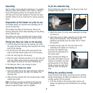
To turn the blower vac on
1. Check the on/off switch is in the off position. This is where
the slide switch is in the back position and the letter “O” is
displayed towards the front of the slide switch.
2. Plug the power cord into an approved electrical
extension cord, and turn the extension cord on.
3. Ensuring the blower vac is directed in a safe direction,
push the on/off switch forward and the blower vac
will start. The letter “I” will be displayed on the rear
section of the slide switch when the switch is in the
“on” position.
Be sure to be holding the blower vac firmly on start up.
9