


14
Section 4 — Maintenance
Air-cooled 11 kW Generators
3.6.5 LOW BATTERY
The microprocessor will continually monitor the bat-
tery voltage and turn on the Low Battery LED if the
battery voltage falls below 11.0 volts for one minute.
Low battery voltage is a non-latching alarm, which
will automatically clear if the battery voltage rises
above 11.0 volts.
The control system will not attempt to start the
engine if there is a low battery condition, however,
if the engine is already running when the low bat-
tery condition occurs, the engine will continue to
run as long as possible.
Battery voltage is NOT monitored during the crank
cycle.
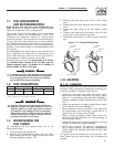
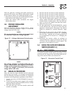
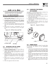
4.1 SYSTEM FUSE
The generator panel’s 15 amp fuse (Figure 4.1) pro-
tects the DC control circuit against overload. The fuse
is wired in series with the battery output lead to the
panel. If the fuse element has melted open, the engine
cannot crank or start. Replace the fuse using only an
identical 15-amp replacement.
4.1.1 7.5 AMP FUSE
The generator panel’s 7.5 amp fuse protects the
accessory outlet against overload. If the fuse element
has melted open, there will not be power at the acces-
sory outlet. Replace the fuse using only an identical
7.5 amp fuse. To remove fuse, push cap down and
rotate counterclockwise.
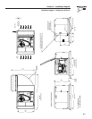
Figure 4.1 – Generator Control Panel
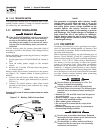
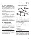
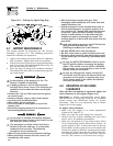
4.2 CHECKING THE ENGINE
OIL LEVEL
For oil capacities, see “Specifications,” Section 1.5.
For engine oil recommendations, see Section 4.3.1.
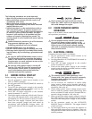
To check the engine oil level, proceed as follows
(Figures 4.2):
1. Start the generator by moving the AUTO/ OFF/
MANUAL switch to the MANUAL position. Allow
it to run for a short while and then shut it down
by moving the switch to the OFF position.
2. Remove the dipstick and wipe it dry with a
clean cloth.
3. Install the dipstick; then, remove it again. The oil
level should be at the dipstick “Full” mark. If nec-
essary, add oil to the “Full” mark only. DO NOT
FILL ABOVE THE “FULL” MARK.
Never operate the engine with the oil level
below the “Add” mark on the dipstick. Doing
this could damage the engine.
4. Install the dipstick.
5. Reset the AUTO/OFF/MANUAL switch to its origi-
nal position.
Figure 4.2 — Oil Dipstick and Fill
Oil Di
p
stic
k
O
il Fil
l
4.3 CHANGING THE ENGINE OIL
4.3.1 ENGINE OIL RECOMMENDATIONS
Use oil of American Petroleum Institute (API) Service
Class SG, SH or SJ. Use all season SAE 5W-30
Synthetic oil. Organic break-in oil is required before
using synthetic oil.
NOTE:
The unit is supplied with “break-in” oil. See the
“Break-in Procedure,” Section 3.1, for the first
required oil change.