


11
With the generator running and loads powered by
generator AC output, turn ON the utility power supply
to the transfer switch. The following should occur:
• After about six seconds, the switch should transfer
loads back to the utility power source.
• About one minute after retransfer, the engine
should shut down.
2.6 VOLTAGE REGULATOR
ADJUSTMENT
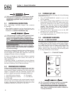
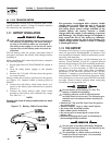
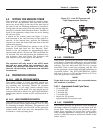
With the frequency between 60-60.5 Hertz, slowly
turn the slotted potentiometer (Figure 2.1) until line
voltage reads 247-252 volts.
NOTE:
The access panel on top of the control panel must
be removed to adjust the voltage regulator.
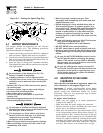
Figure 2.1 – Voltage Adjustment Potentiometer
NOTE:
The voltage regulator is housed inside the gen-
erator's control panel. The regulator maintains a
voltage in direct proportion to frequency at a 2-to-
1 ratio. For example, at 62 Hertz, line-to-neutral
voltage will be 124 volts.
3.1 BREAK-IN PROCEDURE
Once the unit has been installed and all electrical
checks have been made, it is strongly recommended
that the following “Break-in Procedure” be completed
to ensure correct generator operation in the future.
1. Set the generator’s AUTO/OFF/MANUAL switch to
AUTO.
2. Turn OFF the utility power supply to the transfer
switch using the means provided (such as a utility
main line circuit breaker).
3. The unit will start, and the transfer switch will
transfer to standby.
4. Run the unit for one hour at 25% rated load.
5. Run the unit for one hour at 50% rated load.
6. Run the unit for one hour at 75% rated load.
7. Run the unit for one hour at 100% rated load.
8. Turn ON the utility power supply to the transfer
switch, which will allow the transfer switch to
transfer back to utility power. The unit will con-
tinue to run for one minute and then shut down.
9. Allow the unit to cool.
10. Set the generator's AUTO/OFF/MANUAL switch
to OFF. Remove the 7.5A and 15A fuses from the
generator control panel. Disconnect the battery
cables as outlined in “General Hazards” (page
2).
11. Drain the oil and remove the oil filter. Replace
the oil filter according to Section 4.4, “Changing
the Oil Filter”. Replace the oil with synthetic oil
as recommended in Section 4.3, “Changing the
Engine Oil”.
12. Reconnect the battery cables as outlined in
“General Hazards” (page 2) and insert the 5A and
15A fuses into the generator control panel. The
generator is now ready for service.
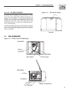
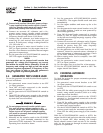
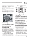
3.2 USING THE AUTO/OFF/MANUAL
SWITCH (FIGURE 3.1)
3.2.1 “AUTO” POSITION
Selecting this switch position activates fully automat-
ic system operation. It also allows personnel to start
and exercise the engine every seven days with the set-
ting of the exercise timer (see Section 3.5).
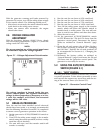
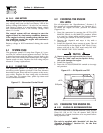
Figure 3.1 – Generator Control Panel
Section 3 — Operation
Air-cooled 11 kW Generators