


1.11 FUEL CONSUMPTION
25 kW Models
Using Natural Gas ........................................441 cu. ft. per hour
Using LP Gas ..............................175 cubic ft.(4.8 gal.) per hour
Fuel pressure for a natural gas set up should be five
inches to 14 inches of water column (0.18 to 0.5
psi) at all load ranges.
Fuel pressure for an LP vapor set up should be 11
inches to 14 inches of water column (0.4 to 0.5
psi) at all load ranges.
NOTE:
Fuel consumption is given at rated maximum con-
tinuous power output when using natural gas
rated at 1000 Btu per cubic foot; or LP gas rated
2520 Btu per cubic foot. Actual fuel consumption
obtained may vary depending on such variables as
applied load, ambient temperature, engine condi-
tions and other environmental factors.
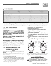
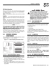
1.12 RECONFIGURING THE FUEL
SYSTEM FOR LP VAPOR
NOTE:
All models are configured for natural gas from the
factory.
To reconfigure the fuel system from NG to LP vapor,
follow these steps:
1. Turn the main gas supply off.
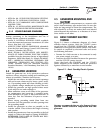
2. Remove the carburetor fuel hose from the outlet
port (Port 1) of the demand regulator (Figure
1.8).
3. Remove the brass hose fitting from the outlet port
(Port 1) of the demand regulator.
4. Remove pipe plug from Port 2.
5. Install brass hose fitting into Port 2.
6. Install pipe plug into Port 1.
7. Connect carburetor gas hose to brass fitting.
8. Tighten all clamps and plugs.
9. Make sure fuel supply is of the proper pressure
and type for configuration.
10. Move dip switch position 4 on the control board
to the off position (LP vapor, see Figure 3.2 and
Section 3.8).
11. Reverse the procedure to convert back to natural
gas.
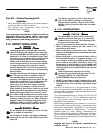
Figure 1.8 — Reconfigure the Fuel System
NOTE:
Port 1 is for NG only and Port 2 is for LP vapor
only. No provision for dual fuel has been made.
Serious injury or damage may occur if not
configured properly. Please consult an author-
ized Generac Service Dealer with any ques-
tions.
!
DANGER
NG FUEL SYSTEM
LP FUEL SYSTEM
Port 1
Port 2
FUEL HOSE
BRASS HOSE
FITTING
OUT
PORT 2
PLUG
FUEL HOSE
BRASS HOSE
FITTING
FUEL INLET
PLUG
OUT
PORT 1
Section 1 — General Information
Guardian Liquid-cooled 25 kW Generator
Generac
®
Power Systems, Inc. 7
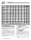
1.10.2 GENERATOR
* Rated power of generator is subject to and limited by such factors as ambient temperature, altitude, engine condition,
and other factors. Engine power will decrease about 3.5% for each 1000 feet above sea level and will decrease an addi-
tional 1% for each 10°F above 60°F. Maximum output power of the generator is limited by maximum engine power.
Single-phase Single-phase Single-phase
Model 005040-0 005053-0 005054-0
Rated Max. Cont. *25 20 15
AC Power Output (kW)
Rated voltage (volts) 120/240 120/240
No. of Rotor Poles 4 4 4
Driven Speed of Rotor 1800 1800 1800
Rotor Excitation System Direct excited brush type Direct excited brush type Direct excited brush type
Type of Stator 4 Wire 4 Wire 4 Wire
Rotor Insulation Class F Class F Class F
Stator Insulation Class H Class H Class H