


Generac
®
Power Systems, Inc. 13
GTS Mode Operation
When in GTS mode, the control board will respond
as follows based on the generator AUTO/OFF/MANU-
AL switch position.
OFF — The generator will not start and run in this
position.
MANUAL — The control board will start and run the
generator whenever the switch is in the manual posi-
tion.
AUTO — The control board will monitor the two-wire
start circuit. When a two-wire start is issued, the con-
trol board will immediately start and run the genera-
tor. Whe the two-wire start is removed the control
board will immediately stop the generator.
NOTE:
If the generator is installed in conjunction with an
engineered GTS type transfer switch, refer to the
applicable transfer switch manual for exact oper-
ating parameters and timing sequences.
For proper battery charger operation, it will be nec-
essary to supply a fused 240VAC utility fed supply to
terminals N1 and N2 in the control panel.
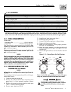
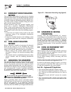
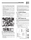
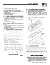
3.2 CONTROL CONSOLE
COMPONENTS
The components of a home standby generator control
console (Figure 3.1) are as follows:
Figure 3.1 - Home Standby Generator Panel
3.2.1 AUTO/OFF/MANUAL SWITCH
Use this three-position switch as follows:
• Set the switch to AUTO for fully automatic opera-
tion. See “Automatic Operation” (Section 3.5).
• Set switch to MANUAL position to crank and start
the generator engine.
• Set switch to OFF position to shut down an oper-
ating engine. With OFF selected, operation will not
be possible.
With switch set to AUTO, engine can crank
and start suddenly without warning. Such
automatic start up normally occurs when utili-
ty source voltage drops below a pre-set level.
To prevent possible injury that might be
caused by such sudden starts, set AUTO/OFF/
MANUAL switch to OFF before working on or
around the unit. Then, place a “DO NOT
OPERATE” tag on control console.
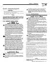
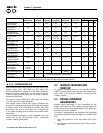
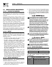
3.2.2 FAULT INDICATOR LEDS
(SEE CHART ON PAGE 14)
These LEDs turn ON when one or more of the follow-
ing engine faults occurs and the engine shuts down.
• Low Oil Pressure
• Overcrank
• Low Battery
• Overspeed/Engine Speed Signal Fault
• High Coolant Temperature/Low Coolant Level
See Section 1.7 for further explanation of engine pro-
tection functions.
3.2.3 15 AMP FUSE
This fuse protects the control console’s DC control
circuit against electrical overload and is located
inside the control panel. If the fuse has melted open
because of an overload, engine cranking and startup
cannot occur. If the fuse needs to be replaced, use
only an identical 15-amp replacement fuse (type
ATO).
3.2.4 5 AMP FUSE
This fuse protects the battery charger against electri-
cal overload and is located inside the control panel. If
the fuse needs to be replaced, use only an identical 5-
amp replacement fuse (type ATO).
NOTE:
This fuse will not remove the + battery input
power from the PCB when it opens. This means
the exercise timer will not be reset.
3.2.5 SET EXERCISE TIME SWITCH
This switch allows programming the generator to
start and exercise automatically. “See Weekly
Exercise Cycle.”
!
DANGER
FOR STAND-BY SERVICE CONNECT OUTPUT OF GENERATOR TO SUITABLY RATED
TRANSFER SWITCH IN ACCORDANCE WITH CANADIAN ELECTRICAL CODE
,
PART I
.
ATTENTION: POUR L'ALIMENTATION DE RESERVE, CONNECTER LA SORTIE DE LA
I
CE A UN COMMUTATEUR DE CALIBRE APPROPRIE
,
CONF
O
CANADIEN DE L'ECTRICITE
,
PREMIERE PARTIE
.
RI
S
K
O
F ELE
C
TRI
C
AL
S
H
OC
K. D
O
N
O
T REM
O
VE
CO
VER. N
O
US
ER
S
ERVI
C
EABLE
PARTS INSIDE. REFER SERVICING TO
Q
UALIFIED SERVICE PERSONNEL
.
THI
S
EMER
G
EN
C
Y P
O
WER
S
Y
S
TEM I
S
DE
S
I
G
NED EX
C
L
US
IVELY F
O
R
OU
TD
OO
R IN
S
TALLATI
O
N
O
NLY
!
N
A
U
T
O
MATI
C
ALLY
S
TART AT ANYTIME WITH
OU
T N
O
TI
C
E.
T
IN
JU
RY REM
O
VE NE
G
ATIVE BATTERY
C
ABLE PRI
O
R T
O
SE
L
O
W
COO
LANT LEVE
L
HI
COO
LANT TEMPERAT
U
R
E
FLA
S
HIN
G
G
REEN LED = N
O
U
TILITY
S
EN
SE
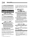
5
FLA
S
HIN
G
RED LED'
S
= EXER
C
I
S
ER N
O
T
S
ET
(
IN AUTO MODE ONLY
)
SOLID GREEN LED = SYSTEM READY, UTILITY POWER O
N
US
E
O
F
S
YNTHETI
C
O
IL I
S
RE
CO
MMENDE
D
(
SEE OWNER'S MANUAL FOR COMPLETE DETAILS
)
LED INDI
C
AT
O
R
S:
RED LED'
S
= INDIVID
U
AL FA
U
L
T
O
VER
C
RAN
K
S
Y
S
TEM READ
Y
L
O
W BATTER
Y
L
O
W
O
IL PRE
SSU
R
E
O
VER
S
PEE
D
O
F
F
MAN
U
A
L
A
U
T
O
START
,
RUN THROUGH THE EXERCISE
C
Y
C
LE AND
S
H
U
TD
O
WN
.
TIME
S
E
T
EXER
C
I
SE
T
O
A
U
T
O
P
OS
ITI
O
N
.
S
WIT
C
H IN "
O
N" P
OS
ITI
O
N F
OR
1
)
PLACE AUTO/OFF/MANUAL SWITC
H
2
)
HOLD "SET EXERCISE TIME
"
T
O
S
ET EXER
C
I
S
ER TIM
E
1
0
S
E
CO
ND
S
. THEN THE
U
NIT WILL
THE EXER
C
I
S
ER I
S
N
O
W
S
ET. ALL
FIVE RED LED'
S
WILL FLA
S
H F
OR
THREE
S
E
CO
ND
S
AND RELEA
S
E
.
ON
WARNIN
G
C
A
U
TI
ON
WARNIN
G
0
F
0653
O
F
F
C
A
U
TI
ON
Section 3 - Operation
Guardian Liquid-cooled 25 kW Generator