


16 Generac
®
Power Systems, Inc.
Section 4 — Maintenance
Guardian Liquid-cooled 25 kW Generator
At this time all five red LEDs will flash for approxi-
mately 10 seconds, then the engine will start and run
for it’s 12 minute exercise period, then shut down.
The generator will now start and run each week at the
same time.
If DC power to the control board is lost, the weekly
exercise setting will be lost. This is indicated by all
five red LEDs continually flashing. In this state the
generator will still start and run in manual mode, or
automatically start and run if utility is lost while in
Auto mode, but it will not perform a weekly exercise
cycle.
If a failure occurs while running in this mode, the five
red LEDs will stop flashing, the individual fault LED
will turn on and the engine will shut down. Once the
AUTO/OFF/MANUAL switch has been switch to OFF,
the individual fault LED will turn OFF and the five
red LEDs will begin flashing to show exercise has still
not been set.
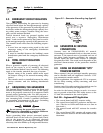
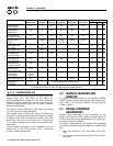
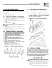
3.8 CONTROL BOARD DIP SWITCH
SETTINGS
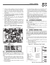
Located on the control board is an eight position DIP
switch (see Figure 3.2). The eight different switches,
are used to configure the control board for the spe-
cific engine and governor being used and are pre-set
at the factory.
If the DIP switch settings are not set correctly,
the generator may not start or operate correct-
ly.
240 VAC can be present within the control
panel.
If it is necessary to select an alternate switch position,
move the AUTO/OFF/MANUAL switch to the OFF
position. Remove the 5 amp and 15 amp fuses in the
generator control panel. Move the DIP switch position
that needs to be changed to its new position. Wait five
seconds, then re-install the 5 and 15 amp fuses.
The ON position is marked on the switch and the fac-
tory settings are also shown in Figure 3.3.
Switch Position 1 — Selects the generator alternator
output frequency and is factory pre-set for 60 Hz.
Switch Position 2 — Selects the type of transfer
switch and is factory pre-set for an automatic trans-
fer switch (ATS).
Switch Position 3 — Selects the type of governor
control used and is factory pre-set for stepper motor
control.
Switch Position 4 — Selects the type of fuel being
used and is factory pre-set for natural gas (NG).
Switch Position 5 — Selects the engine displacement
and is factory pre-set for a 2.5 liter (2.5L) engine.
Switch Position 6 — Selects the number of engine
cylinders and is factory pre-set for four cylinders.
Switch Position 7 — Selects the direction of rotation
of the governor stepper motor and is factory pre-set
for CCW rotation (rotation is observed looking at the
stepper shaft as it move from closed throttle to open
throttle).
Switch Position 8 — Selects whether the control is
in the Normal Mode of operation or Test Mode. In the
Normal Mode of operation, pre-determined governor
gains are used and the gain trimpots on the control
board (Gain, Stability, and Differential) are not active
and have no effect on the gains. In Test Mode the gain
trimpots are active and can be adjusted. See Section
3.4.
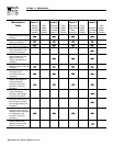
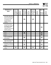
4.1 MAINTENANCE PERFORMED BY
AUTHORIZED SERVICE FACILITIES
A. EVERY THREE MONTHS
1. Check battery condition.
2. Inspect and test fuel system.
3. Check transfer switch.
4. Inspect exhaust system.
5. Check engine ignition system.
6. Check fan belts.
B. ONCE EVERY SIX MONTHS
1. Test Engine Safety Devices (low oil pressure, low
coolant level, high coolant temperature).
C. ONCE ANNUALLY
1. Test engine governor; adjust or repair, if needed.
2. Clean, inspect generator.
3. Flush cooling system.
D. FIRST 100 OPERATING HOURS
1. Change engine oil and oil filter. After initial
change, service engine oil and filter at 150 oper-
ating hours or six months, whichever comes first.
2. Retorque cylinder head (see torque specs).
3. Retorque intake and exhaust manifold (see
torque specs).
E. EVERY 500 OPERATING HOURS
1. Service air cleaner.
2. Check starter.
3. Check engine DC alternator.
!