


Generac
®
Power Systems, Inc. 15
Section 3 - Operation
Guardian Liquid-cooled 25 kW Generator
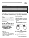
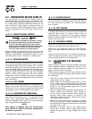
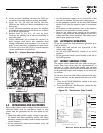
3. Under no load condition, increase the GAIN pot
as much as possible without causing instability.
4. Apply 1/4, 1/2, 3/4 and full load to the unit.
Decrease the GAIN pot if there is instability at any
load point.
5. Under full load condition, increase the stability
pot until the unit returns to 60 Hertz (or 50 Hertz
in 50 Hertz applications).
6. Reduce load to 3/4, 1/2, 1/4 and no load.
Decrease the stability pot if there is instability at
any load point.
7. Adjust differential pot to make the recovery to
load changes even faster and minimize load
change undershoot and overshoot. If it is set too
high, it may introduce oscillations at some load.
It can be set to zero (full CCW) if a small amount
causes oscillations at some load.
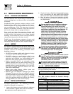
Figure 3.2 — Engine Governor Adjustment
3.5 RETRANSFER AND SHUTDOWN
When utility power source voltage has been restored,
electrical loads may be transferred back to that
source and the generator can be shut down as fol-
lows:
• Verify that utility power supply voltage to the trans-
fer switch has been positively turned Off, using
whatever means provided (such as utility main line
circuit breaker).
• Set the generator’s main circuit breaker to its Off
or Open position.
• Let the generator engine run at no-load for a few
minutes, to stabilize internal unit temperatures.
• On the generator console, set the Auto/Off/ Manual
switch to Off. Wait for engine to come to a complete
stop.
• For transfer to utility position, refer to the Owner’s
Manual of the particular transfer switch.
• Turn on the utility power supply to the transfer
switch, using whatever means provided (such as a
utility main line circuit breaker). The utility power
source now powers the loads.
3.6 AUTOMATIC OPERATION
To set the system for fully automatic operation, pro-
ceed as follows:
• Check that load circuits are connected to the
utility power supply.
• Set the AUTO/OFF/MANUAL switch to its AUTO
position.
• Set the generator main circuit breaker to its ON or
CLOSED position.
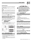
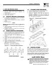
3.7 WEEKLY EXERCISE CYCLE
The engine control board will start and run the gen-
erator once every seven days for approximately 12
minutes. If utility should fail during this exercise
period, the engine control board will transfer the load
to the generator output and continue to run until util-
ity returns.
On the day, and at the time of day chosen for the gen-
erator to exercise, set the weekly exercise cycle as fol-
lows:
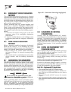
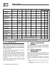
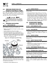
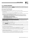
1. Place the AUTO/OFF/MANUAL switch in the auto
position (Figure 3.3).
2. Press and hold the “Set Exercise” switch for five
seconds, then release.
Figure 3.3 - “Set Exercise Time” Switch
FOR STAND-BY SERV
TRANSFER SWITCH I
N
ATTENTION: POUR L'
I
CE A UN CO
M
CA
N
RI
S
K
O
F ELE
C
TRI
C
A
L
PARTS INSIDE.
R
THIS EMERGEN
N
A
U
T
O
MATI
CA
IN
JU
RY REM
O
L
O
W
COO
LANT LEVE
L
HI
COO
LANT TEMPERAT
U
R
E
FLA
S
HIN
G
G
REEN LED = N
O
U
TILITY
S
EN
SE
5
FLA
S
HIN
G
RED LED'
S
= EXER
C
I
S
ER N
O
T
S
E
T
(
IN AUTO MODE ONLY
)
SOLID GREEN LED = SYSTEM READY, UTILITY POWER O
N
(
SEE OWNER'S MANUAL FOR COMPLETE DETAILS
)
LED INDI
C
AT
O
R
S:
RED LED'
S
= INDIVID
U
AL FA
U
L
T
O
VER
C
RAN
K
S
Y
S
TEM READ
Y
L
O
W BATTER
Y
L
O
W
O
IL PRE
SSU
R
E
O
VER
S
PEE
D
O
F
F
MAN
U
A
L
A
U
T
O
START
,
RUN THROUGH THE EXERCISE
C
Y
C
LE AND
S
H
U
TD
O
WN
.
TIME
S
E
T
EXER
C
I
SE
T
O
A
U
T
O
P
OS
ITI
O
N
.
S
WIT
C
H IN "
O
N" P
OS
ITI
O
N F
OR
1
)
PLACE AUTO/OFF/MANUAL SWITC
H
2
)
HOLD "SET EXERCISE TIME
"
T
O
S
ET EXER
C
I
S
ER TIM
E
1
0
S
E
CO
ND
S
. THEN THE
U
NIT WILL
THE EXER
C
I
S
ER I
S
N
O
W
S
ET. ALL
FIVE RED LED'
S
WILL FLA
S
H F
OR
THREE
S
E
CO
ND
S
AND RELEA
S
E
.
ON
0
F
0653
O
F
F