


14 Generac
®
Power Systems, Inc.
3.2.6 SYSTEM READY LED
The System Ready LED (green) has two main pro-
poses. First, the LED will be ON when the
AUTO/OFF/MANUAL switch is in the AUTO position,
utility is present, and there are no system alarms.
This ON state indicates the system is fully ready for
automatic operation.
The system ready LED will be OFF when the switch
is in the manual or OFF positions.
The system ready LED is also used to indicate the
presence of utility sensing at the PCB when the switch
is either in the AUTO or MANUAL modes. The LED
will flash at the rate of 1/2 second on, 1/2 second off
if the utility sensing level is below the transfer back
threshold.
This secondary function is only available with dip
switch two in the OFF position (ATS - automatic
transfer switch application).
3.3 MANUAL TRANSFER AND
START-UP
To transfer electrical loads to the Standby (EMER-
GENCY) power source side and start the engine man-
ually, refer to the Owner’s Manual of the particular
transfer switch.
3.4 ENGINE GOVERNOR
ADJUSTMENTS
Engine speed governing is also controlled by the
engine control board. The engine governor has been
set by the factory during final testing of the generator
and should not be adjusted.
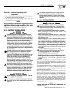
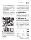
If, however, adjustments are necessary, the following
procedure should be followed (Figure 3.2 and Section
3.8):
1. Move dip switch 8 to the test mode (OFF posi-
tion).
2. Set all three potentiometers (pots) fully counter-
clockwise.
Section 3 - Operation
Guardian Liquid-cooled 25 kW Generator
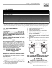
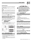
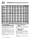
Condition System Low Low High Over Over Switch Position
Ready (Green) Bat (Red) Oil (Red) Temp (Red) Speed (Red) Crank (Red) Manual Auto Off
Generator Switch is OFF X OFF OFF OFF OFF O
in the OFF Mode.
System Ready for ON X OFF OFF OFF OFF O
Automatic Start
Generator Switch is OFF X OFF OFF OFF OFF O
in the MANUAL Mode
Weekly Exerciser X Flashing Flashing Flashing Flashing Flashing O O O
is not set (-----------------------------------1 sec rate---------------------------------------)
Battery Voltage <12V X ON OOO
for >1 minute (Non-latching)
Battery Voltage <6V X ON OO
Unit Shutdown due OFF X ON O O
to Low Oil Pressure
Unit Shutdown due OFF X ON O O
to High Temperature
Unit Shutdown due OFF X ON O O
to Engine Overspeed
Unit Failed to Start OFF X ON O O
during it’s Crank Cycle
Utility Voltage is Flashing X OO
<45% of Nominal 1 sec rate
Engine Speed Signal Fault OFF X Flashing O O
Control Board is OFF X The five RED LED’s will turn on one at a time O O O
in GTS Mode
X = indicates that the LED can be ON or OFF depending on the operating conditions.