


10 Generac
®
Power Systems, Inc.
2.5 EMERGENCY CIRCUIT ISOLATION
METHOD
This prevents overloading the generator by keeping
electrical loads below the wattage/amperage capacity
of the generator. If the generator is powering only crit-
ical loads, within the wattage/amperage capacity, dur-
ing utility power outages, consider using the emer-
gency circuit isolation method.
Critical electrical loads are grouped together and
wired into a separate “Emergency Distribution
Panel.” Load circuits powered by that panel are with-
in the wattage/amperage capacity of the generator set.
The transfer switch must meet the following require-
ments:
• It must have an ampere rating equal to the total
amperage rating of the emergency distribution
panel circuit.
• It must be installed between the building’s main
distribution panel and the emergency distribution
panel.
2.6 TOTAL CIRCUIT ISOLATION
METHOD
When a generator capable of powering all electrical
loads in the circuit is to be installed, the “Total
Circuit Isolation Method” may be used. The following
apply to the transfer switch in this type of system.
• Ampere rating of the transfer switch must equal
the ampere rating of the normal incoming utility
service.
• The transfer switch is installed between the utility
service entrance and the building distribution
panel.
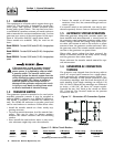
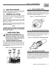
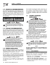
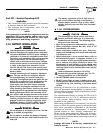
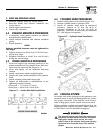
2.7 GROUNDING THE GENERATOR
The National Electrical Code requires the frame and
external electrically conductive parts of this equip-
ment to be properly connected to an approved earth
ground and/or grounding rods. For that purpose, a
GROUND LUG (Figure 2.2) is provided on the gener-
ator mounting base. Consult a qualified electrician
for grounding requirements in the area. Grounding
procedures must meet local regulations.
Do not connect the ground wire to any pipe
that carries a flammable or explosive substance
– FIRE or an EXPLOSION may result.
Proper grounding helps protect personnel against
electrical shock in the event of a ground fault condi-
tion in the generator or in connected electrical
devices. In addition, grounding helps dissipate static
electricity that often builds up in ungrounded devices.
Figure 2.2 – Generator Grounding Lug (typical)
2.8 GENERATOR AC NEUTRAL
CONNECTIONS
Generac uses an UNGROUNDED AC neutral.
Grounding is recommended only at the main service
entrance. If the neutral wire is grounded and one of
the phase loads becomes grounded, the excessive
current opens the load circuit breaker or collapses
the generator field. The actual result depends on the
electrical characteristics of the particular installed
generator.
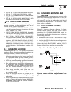
2.9 USING AN ENGINEERED “GTS”
TRANSFER SWITCH
When required, the pre-packaged standby generator
can be installed with an engineered Generac “GTS”
type automatic transfer switch.
In this application, the engineered GTS is responsi-
ble for utility sensing, weekly exercising, and load
transferring.
Position two of the eight-position dip switch is used to
turn over this control to the engineered GTS.
In order for the battery charger to work, it is neces-
sary to provide a fused 240 VAC utility source to the
N1 and N2 terminals in the control panel.
Pos2 ON — Engineered GTS Application
• The control board will NOT monitor utility.
• The control board will NOT perform a weekly exer-
cise. (The five red LEDs will flash one at a time in
this mode.)
• The control board will NOT activate the transfer
output.
• The control board WILL monitor all engine condi-
tions and shut down on all the faults listed in this
document.
DANGER
Section 2 — Installation
Guardian Liquid-cooled 25 kW Generator