


4 Generac
®
Power Systems, Inc.
1.1 GENERATOR
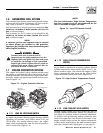
This equipment is a liquid-cooled, engine-driven gen-
erator set. The generator is designed to supply elec-
trical power that operates critical electrical loads
during utility power failure. The unit has been facto-
ry-installed in a weather resistant, all metal enclosure
and is intended for outdoor installation only. Use this
generator as a source of electrical power for the oper-
ation of 120 and/or 240VAC, single-phase loads.
If this generator is used to power electrical
load circuits normally powered by a utility
power source, it is required by code to install
a transfer switch. The transfer switch must
effectively isolate the electric system from the
utility distribution system when the generator
is operating (NEC 701). Failure to isolate an
electrical system by such means results in
damage to the generator and may also result
in injury or even death to utility power work-
ers due to backfeed of electrical energy.
1.2 TRANSFER SWITCH
This generator system includes a matched 200 amp
automatic transfer switch which is intended to be
used in conjunction with the generator. It is supplied
in a NEMA 3R enclosure. The NEMA 3R enclosure is
weather resistant and can be used indoors or out-
doors. Follow these rules:
• Install the transfer switch on a firm, sturdy sup-
porting structure.
• To prevent switch distortion, level the switch if nec-
essary. This can be done by placing washers
between the switch enclosure and the mounting
surface.
• Never install the switch where water or any corro-
sive substance might drip onto the enclosure.
• Protect the switch at all times against excessive
moisture, dust, dirt, lint, construction grit and cor-
rosive vapors.
1.3 AUTOMATIC SYSTEM OPERATION
When this generator, along with a transfer switch, has
been installed and interconnected, a circuit board in
the generator panel constantly monitors UTILITY
power source voltage. Should that voltage drop below
a preset value, and remain at such a low state for a
preset amount of time, the generator cranks and
starts. After the generator starts, the transfer switch
transfers load circuits so the generator can power
them.
When utility source voltage has been restored, the
switch re-transfers back to the UTILITY source volt-
age and the generator then shuts down.
Please reference the transfer switch manual for spe-
cific information.
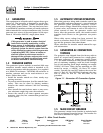
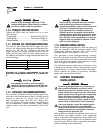
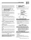
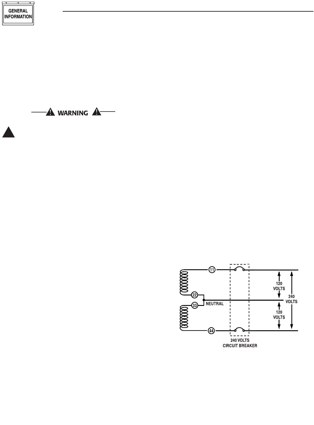
1.4 GENERATOR AC CONNECTION
SYSTEMS
The generator was shipped from the factory with its
stator AC output leads connected in a single-phase,
three-wire generator AC connection system (Figure
1.1). The stator assembly in this system consists of a
pair of stationary windings, with two leads brought
out of each winding. Each single winding can supply
120VAC, 60 Hertz. When the two windings are con-
nected in series, a 240VAC, 60 Hertz AC output
results. Typically the two HOT leads in the circuit are
wires 11 and 44. The NEUTRAL leads are the junc-
tion of Wires 22 and 33. The NEUTRAL is not
grounded.
Figure 1.1 - Generator AC Connection System
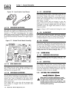
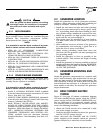
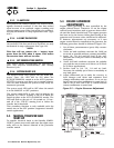
1.5 MAIN CIRCUIT BREAKER
The generator’s main circuit breaker is included with
the unit as shipped from the factory. The breaker for
this unit is described in Figure 1.2.
!
Section 1 - General Information
Guardian 40kW Liquid-cooled Generators
Model Rating Phase Actual Current C/B Rating* Circuit Breaker
004992-0 37,000 NG 1 154.2 200 200A QN2
40,000 LP 1 166.7 200 200A QN2
* Amp Rating of C/B structured under model.
Figure 1.2 - Main Circuit Breaker