


Generac
®
Power Systems, Inc. 13
Make sure the generator battery is fully charged, prop-
erly installed and interconnected, and ready for use.
Check to ensure that there are no loose electrical con-
nections. Restrain any loose wires to keep them clear
of any moving generator set components.
3.1 USING AN ENGINEERED “GTS”
TRANSFER SWITCH
When required, the pre-packaged standby generator
can be installed with an engineered Generac “GTS”
type automatic transfer switch.
In this application, the GTS is responsible for utility
sensing, weekly exercising, and load transferring.
Position two of the four-position dip switch is used to
turn over this control to the GTS.
Pos2 ON — GTS Application
• The control board will NOT monitor utility.
• The control board will NOT perform a weekly exer-
cise. (The five red LEDs will not flash in this
mode.)
• The control board will NOT activate the transfer
output.
• The control board WILL monitor all engine condi-
tions and shut down on all the faults listed in this
document.
Pos2 OFF — ATS Application (Included switch)
• The control board will perform all of the automat-
ic features listed in this document.
• The two-wire start connections should NOT be
used.
GTS Mode Operation
When in GTS mode, the control board will respond
as follows based on the AUTO/OFF/MANUAL switch
position.
OFF — The generator will not start and run in this
position.
MANUAL — The control board will start and run the
generator whenever the switch is in the manual posi-
tion.
AUTO — The control board will monitor the two-wire
start circuit. When a two-wire start is issued the con-
trol board will immediately start and run the genera-
tor. Whe the two-wire start is removed the control
board will immediately stop the generator.
NOTE:
If the generator is installed in conjunction with an
engineered GTS type transfer switch, refer to the
applicable transfer switch manual for exact oper-
ating parameters and timing sequences.
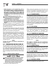
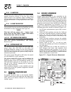
3.2 CONTROL CONSOLE
COMPONENTS
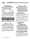
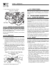
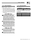
The components of a home standby generator control
console (Figure 3.1) are as follows:
Figure 3.1 - Home Standby Generator Panel
3.2.1 AUTO/OFF/MANUAL SWITCH
Use this three-position switch as follows:
• Set the switch to AUTO for fully automatic opera-
tion. See “Automatic Operation” (Section 3.5).
• Set switch to MANUAL position to crank and start
the generator engine.
• Set switch to OFF position to shut down an oper-
ating engine. With OFF selected, operation will not
be possible.
With switch set to AUTO, engine can crank
and start suddenly without warning. Such
automatic start up normally occurs when utili-
ty source voltage drops below a pre-set level.
To prevent possible injury that might be
caused by such sudden starts, set AUTO/OFF/
MANUAL switch to OFF before working on or
around the unit. Then, place a “DO NOT
OPERATE” tag on control console.
3.2.2 FAULT INDICATOR LEDS
These LEDs turn ON when one of the following
engine faults occurs and the engine shuts down.
• Low Oil Pressure
• Overcrank
• Low Battery
• Overspeed/RPM Sensor Loss
• High Coolant Temperature/Low Coolant Level
See Section 1.7 for further explanation of engine pro-
tection functions.
!
DANGER
E
U
S
UU
F
F
E
U
S
UU
F
(
SEE OWNER'S MANUAL FOR COMPLETE LED DETAILS
)
5
FLA
S
HIN
G
RED LED'
S
= EXER
C
I
S
ER N
O
T
S
E
T
FLA
S
HIN
G
G
REEN LED = N
O
U
TILITY
S
EN
SE
TO SET EXERCISER TIME
1) PLACE AUTO/OFF/MANUAL SWITCH TO AUTO POSITION.
(
IN AUTO MODE ONLY
)
SOLID GREEN LED = SYSTEM READY, UTILITY POWER O
N
OFF
EXER
C
I
SE
TIME
ON
S
E
T
LED INDI
C
AT
O
R
S:
RED LED'
S
= INDIVID
U
AL FA
U
L
T
M
AN
U
A
L
O
F
F
A
U
T
O
0E7194
O
VER
C
RAN
K
A
U
T
O/O
FF
/
MAN
U
A
L
S
WIT
CH
1
5
A F
USE
MAI
N
P
O
WE
R
4A F
USE
BATTERY
C
HAR
G
E
R
S
E
T
EXE
C
I
S
E
R
TIME
S
WIT
CH
RED LED
G
REEN LE
D
Section 3 - Operation
Guardian 40kW Liquid-cooled Generators