


Generac
®
Power Systems, Inc. 11
2.9 TRANSFER SWITCH SIGNAL
CONNECTIONS
2.9.1 PRE-PACKAGED ATS
If the generator is to be installed with a pre-packaged
transfer switch, it is necessary to connect the control
wires to the generator and set position two of the
four-position dip switch to OFF.
Setting switch two to OFF allows the control PCB to
perform the ATS control functions.
Control system interconnections consist of N1 and
N2, and leads 23 and 194. Control system intercon-
nection leads must be run in a conduit that is sepa-
rate from the AC power lead. Recommended wire
gauge sizes for this wiring depends on the length of
the wire, as recommended below:
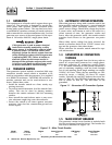
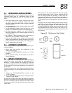
2.9.2 GTS-TYPE ATS
If the generator is to be installed with an engineered
automatic transfer switch, such as a Generac GTS-
type switch, it is necessary to connect the two-wire
start control system.
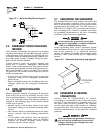
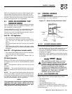
Connect the two-wire start signal from the automatic
transfer switch to the automatic start connection,
which is located in the middle, on the bottom, inside
the control panel. Match wires 178 and 183 in the
transfer switch to 178 and 183 on the terminal strip
in the control panel. The conductors for the two-wire
start circuit must be in their own conduit. (See
Section 3.1 for further explanation.)
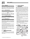
NOTE:
It will be necessary to provide a UTILITY supply to
the integral battery charger. This battery charger
is located in the engine generator control panel.
Locate the six position terminal strip in the con-
trol panel. Connect a 240 VAC UTILITY supplied
source to terminals labeled N1 and N2. The 240
VAC circuit should be protected by a 15A maxi-
mum rated circuit breaker.
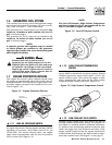
2.10 BATTERY INSTALLATION
Standby generators installed with automatic
transfer switches will crank and start automati-
cally when NORMAL (UTILITY) source voltage is
removed or is below an acceptable preset level.
To prevent such automatic start-up and possible
injury to personnel, do not connect battery
cables until certain that normal source voltage
at the transfer switch is correct and the system
is ready to be placed into operation.
Storage batteries give off explosive hydrogen
gas. This gas can form an explosive mixture
around the battery for several hours after
charging. The slightest spark can ignite the gas
and cause an explosion. Such an explosion can
shatter the battery and cause blindness or
other injury. Any area that houses a storage
battery must be properly ventilated. Do not
allow smoking, open flame, sparks or any spark
producing tools or equipment near the battery.
Battery electrolyte fluid is an extremely caustic
sulfuric acid solution that can cause severe
burns. Do not permit fluid to contact eyes, skin,
clothing, painted surfaces, etc. Wear protective
goggles, protective clothing and gloves when
handling a battery. If fluid is spilled, flush the
affected area immediately with clear water.
Do not dispose of the battery in a fire. The bat-
tery is capable of exploding.
Do not open or mutilate the battery. Released
electrolyte can be toxic and harmful to the skin
and eyes.
The battery represents a risk of high short circuit
current. When working on the battery, always
remove watches, rings or other metal objects,
and only use tools that have insulated handles.
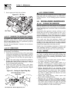
2.10.1 VENTED BATTERIES
The electrolyte is a dilute sulfuric acid that is
harmful to the skin and eyes. It is electrically
conductive and corrosive. The following proce-
dures are to be observed:
• Wear full eye protection and protective clothing,
• Where electrolyte contacts the skin, wash it off
immediately with water,
• Where electrolyte contacts the eyes, flush thor-
oughly and immediately with water and seek med-
ical attention, and
!
!
!
!
DANGER
Section 2 — Installation
Guardian 40kW Liquid-cooled Generators
MAXIMUM WIRE LENGTH RECOMMENDED WIRE
SIZE
460 feet (140m) No. 18 AWG.
461 to 730 feet (223m) No. 16 AWG.
731 to 1,160 feet (354m) No. 14 AWG.
1,161 to 1,850 feet (565m) No. 12 AWG.