


29
• Wiring must be of adequate size, have approved
insulative qualities and be properly supported.
• Conduit and wire openings into the generator com-
partment (if used) must be vapor-sealed to prevent
entry of flammable, explosive or poisonous gases
into the vehicle.
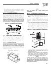
2.6.1 ELECTRICAL JUNCTION BOX
Install an approved, square electrical junction box
with a blank cover on the interior or exterior wall
of the area planned for installation of the generator
(NOT on the generator). Route the generator's AC
output leads into this junction box through approved
flexible conduit. This is the point of first termination
for generator AC output leads.
2.6.2 WIRING
• Wiring should be of stranded copper to reduce the
chance that vibration may cause breakage.
• Wire gauge size should be large enough to handle at
least 115 percent of the installed generator's rated
maximum current.
• Neutral conductors must be the same size as other
leg wires.
• Route power supply conductors from generator AC
output leads (white), (black) and the green ground
wire through approved flexible conduit to the elec-
trical junction box on the compartment wall.
If flexible metal conduit is used between the gen-
erator and the compartment junction box, the con-
duit end that terminates the compartment junction
box must be vapor-sealed. Flexible metal conduit
is NOT vapor tight along its entire length.
• From the junction box, route power supply wires
through approved conduit to either (a) double-pole,
double-throw transfer switch, or (b) approved iso-
lation receptacle. Connecting to a transfer switch
or isolation receptacle must prevent vehicle electri-
cal circuits from being connected to two different
power supplies at the same time (such as genera-
tor and dockside power).
• Conductors must be rated 221° F (105° C) or must
be of a larger conductor size.
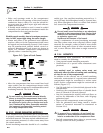
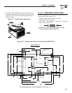
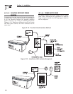
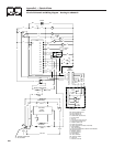
2.6.3 GENERATOR AC CONNECTIONS
Generator AC output leads (BLACK) “hot” and
(WHITE) grounded neutral come out of the generator
as shown in Figure 2.13. There is also a green lead
that connects to ground in the junction box of the
recreational vehicle.
Figure 2.13 – Generator AC Output Leads
483.1
AC OUTPUT
HARNESS
REMOTE PANEL
CONNECTOR
BATTERY
CONNECTIONS
FUEL FILTER
I
t
r
e
,
e
h
i
t
w
a
n
c
.
-
s
m
,
I
e
W
W
y
s
S
r
o
P
w
e
A
C
N
R
E
G
E
t
TM
Leads BLACK to WHITE are protected against over-
load by a 30-amp circuit breaker (CB1). Use this
line-to-neutral connection separately to operate 120-
volt, single-phase, 60 Hertz, AC loads requiring up to
3,600 watts (3.6 kW) of power.
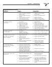
Do NOT connect electrical loads in excess of any
circuit breaker rating or problems will develop
with circuit breaker tripping, which causes a loss
of AC output. Also, do NOT exceed the gener-
ator's rated wattage capacity. Add the watts
or amperes of all lighting, appliance, tool and
motor loads the generator will operate at one
time. This total should be less than the unit's
rated wattage/amperage capacity.
2.6.4 CONDUIT
Route the connections between the generator and the
junction box through approved, flexible conduit. The
following general rules apply:
• Cut wiring to the required length and allow extra
wire for junction box connections.
• Carefully prepare conduit ends to prevent sharp
edges from cutting through wiring insulation.
• Route conduit so it does not interfere with genera-
tor movement.
• If using metallic conduit, vapor seal the end of the
conduit where it enters the junction box. Do this
because flexible metallic conduit is not vaporproof
along its entire length.
Section 2 – Installation
Recreational Vehicle Generator