


23
• The installer must make certain that the selected
location will permit adequate cooling and ventilat-
ing airflow to be supplied.
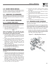
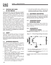
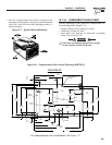
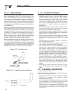
2.1.4 GENERATOR RESTRAINT
Use four 5/16"-18 hardened steel bolts (Grade 5) to
fasten the generator to the supporting frame or the
support tubing. These bolts must pass through (a)
the generator mounting base, (b) the compartment
floor (if a compartment is used) and (c) the support-
ing framework (Figure 2.3). All bolts must be long
enough so that when tight, at least three threads are
visible past the retaining lock nuts. Refer to Section
2.2 for the location of the generator mounting holes.
Figure 2.3 – Typical Generator Restraint
2.2 GENERATOR COMPARTMENTS
Whether the generator set is being installed inside a
compartment specifically manufactured to house a
generator or inside a compartment that the installer
constructs, the compartment must meet certain spec-
ifications as outlined in the following sections:
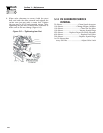
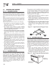
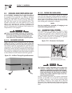
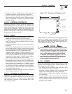
2.2.1 COMPARTMENT SIZE
Plan the compartment size carefully. Provide a mini-
mum clearance of 1/2 inch (13 mm) on the front and
top, 1/2 inch (25 mm) on the sides, and 1/2 inch (13
mm) from the back for air circulation AFTER the
compartment has been lined with metal and sound
insulation (Figure 2.4).
Figure 2.4 – Clearances
1" Clearance
in Back
1/2" Clearance on Top
1" Each Side
1/2"
in Front
Insulation
Plywood
Compartment
18" Clearance Recommended
Below (Minimum 12")
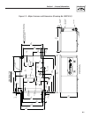
NOTE:
Refer to “Figure 1.2 – Major Features and
Dimensions”.
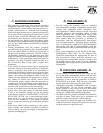
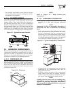
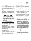
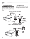
2.2.2 COMPARTMENT CONSTRUCTION
• The generator compartment should be either con-
structed of, or lined with, 26-gauge galvanized
steel.
NOTE:
Aluminum is NOT an acceptable alternative to
galvanized steel due to aluminum’s low melting
point.
• If the compartment is lined with galvanized steel,
it may be constructed of any material. The manu-
facturer recommends that the compartment be
constructed of 1/2-inch thick plywood (not strand-
board), with the floor made of a double thickness
of 1/2-inch plywood with the grain of the wood at
cross section for added strength (Figure 2.5).
Figure 2.5 – Typical Compartment Construction
• If constructing a compartment, line the exterior
(underside) of the compartment floor with 26-
gauge galvanized steel.
• All seams, splices and joints of the compartment
walls (unless vapor tight by design) should be
caulked to prevent poisonous, flammable or explo-
sive vapors from entering the vehicle interior.
NOTE:
Caulking must be done so that the caulking mate-
rial will stay in place permanently. Pressing such
materials as putty tape onto joints and seams is
NOT acceptable. A high quality silicone rubber base
sealant is recommended.
Section 2 – Installation
Recreational Vehicle Generator