


Table of Contents
Guardian Liquid-cooled 10 kW, 15 kW, 20 kW and 25 kW Generators
Generac
®
Power Systems, Inc. 1
INTRODUCTION
............................................................
SAFETY RULES ........................................................................2
Section 1
GENERAL INFORMATION ........................................................4
Generator ....................................................................................4
Automatic System Operation ......................................................4
Generator AC Connection Systems ............................................4
Main Circuit Breaker....................................................................5
Generator Fuel System ..............................................................5
Engine Protective Devices ..........................................................5
Unpacking....................................................................................6
Generator Specifications ............................................................6
Lifting the Generator ..................................................................7
Engine Specifications ..................................................................7
Fuel Consumption ......................................................................7
Lifting the Generator ..................................................................7
Engine Oil Recommendations ....................................................7
Before Installation........................................................................8
Section 2
STANDBY GENERATOR INSTALLATION ................................9
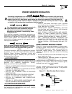
Basic Standby Electric System..............................................................9
Emergency Circuit Isolation Method....................................................10
Total Circuit Isolation Method ..............................................................10
Grounding the Generator ....................................................................10
Generator AC Neutral Connections ....................................................10
Transfer Switch Start Signal Connections ..........................................10
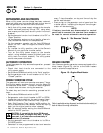
Battery Installation ..............................................................................10
Preparation Before Start-Up ................................................................11
Section 3
OPERATION ............................................................................12
Using a Standard “GTS” Transfer Switch ..................................12
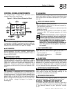
Control Console Components ..................................................13
Manual Transfer and Startup ....................................................13
Retransfer and Shutdown..........................................................14
Automatic Operation..................................................................14
Weekly Exercise Cycle..............................................................14
Engine Heater ..........................................................................14
Section 3
MAINTENANCE........................................................................15
Maintenance Performed by
Authorized Service Facilities ....................................................15
Overload Protection for Engine DC Electrical System ..............15
Checking Fluid Levels ..............................................................15
Maintenance Owner/Operator Can Perform..............................16
Miscellaneous Maintenance......................................................17
TROUBLESHOOTING ..............................................................18
Section 4
NOTES ......................................................................................19
Section 5
WIRING DIAGRAMS AND SCHEMATICS..........................20-25
Section 6
EXPLODED VIEWS AND PARTS LISTS ............................26-43
Section 7
INSTALLATION DRAWINGS ..............................................44-45
Section 8
WARRANTY.......................................................46 - Back Cover
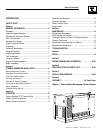
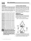
Figure 1- Water Cooled Emergency Power System