


8 Generac
®
Power Systems, Inc.
BEFORE INSTALLATION
Before installing this equipment, check the ratings of
both the generator and the transfer switch. Read
“Emergency Isolation Method” and “Total Circuit
Isolation Method” in the installation manual (Part No.
079699).
The generator’s rated wattage/amperage capacity must
be adequate to handle all electrical loads that the unit
will power. You may have to group the critical (essential)
loads together and wire them into a separate “emer-
gency” distribution panel.
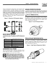
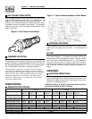
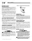
This generator can be installed in conjunction with a
standard Generac “GTS” type transfer switch, if
desired.
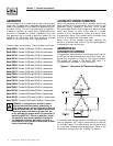
The standard transfer switch has no sensing or con-
trolling circuit boards. Instead, the generator control
console houses a “Control Module Assembly”, which
controls all phases of operation, including engine start
up and load transfer.
Section 1 — General Information
Guardian Liquid-cooled 10 kW, 15 kW, 20 kW and 25 kW Generators