


Maintenance
Owner’s Manual for Stationary Emergency Generators 45
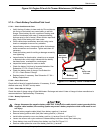
5.11 — Lube Oil Maintainer System
5.11.1— Description
NOTE: Oil reservoir is empty when shipped from factory. Fill with clean engine oil to activate the system.
The 36 kW, 45 kW, and 60 kW models are equipped with a Lube Oil Maintainer System. The system is installed at the
factory and calibrated at the factory to the correct engine-running crankcase oil level. As needed, the system keeps the
engine lubricating oil full by automatically adding clean oil from the oil supply tank.
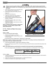
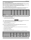
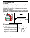
See A of Figure 5-17. The green bar observed through the viewing lens shows the normal oil level operating range of
the Lube Oil Maintainer Regulator during engine running operation. When the oil level is within the green bar, the inter-
nal float holds the inlet valve closed to keep the crankcase oil at the current level.
As the engine uses oil, the float drops to open the inlet valve and allow clean oil to be supplied to the crankcase,
replenishing engine oil to the full mark indicated on the oil dipstick. The float then rises with the crankcase oil level until
it reaches a point where the inlet valve closes.
When the oil level as observed through the viewing lens is below the normal operating range green bar, it is an indica-
tion that the oil supply tank is low or the oil inlet screen is clogged. See B of Figure 5-17.
NOTE: It is normal for the oil level to be above the normal operating range green bar when engine is not run-
ning.
Figure 5-17. Lube Oil Maintainer Regulator
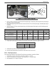
NOTE: When changing engine oil, always close the shutoff
valve to avoid draining the clean oil in the oil supply tank with
the crankcase oil. See Figure 5-19.
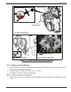
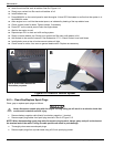
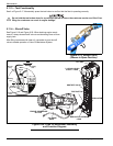
5.11.2— Fill Oil Supply Tank
1. Rotate plastic cover counter-clockwise and remove from top
of enclosure. See Figure 5-18.
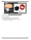
2. Remove fill cap at top of oil supply tank (Figure 5-20.).
3. Add clean engine oil to oil supply tank (2-1/2 gallons [9.46
liters] capacity).
4. Install fill cap at top of oil supply tank.
5. Install plastic cover at top of enclosure and rotate clockwise
until tight.
Green Bar
Test
A
B
Normal
Operating
Range
Low Zone
Viewing Lens
Button
Oil Inlet
Screen
Figure 5-18. Access Oil Supply Tank