


Specifications
Owner’s Manual for Stationary Emergency Generators 9
2.7 — Reconfiguring the Fuel System
While some models are created fuel specific for either Natural gas (NG) or Liquid Propane vapor (LPV) and are not fuel
convertible, others are configured at the factory for NG, but are field convertible to LPV. Units fitted with a dual fuel car-
buretion system are generally configured for the selected fuel source during installation.
To reconfigure the fuel system, change the jet in the demand regulator, and then navigate to the appropriate menu to
assign the new fuel type. Before proceeding, be aware that the fuel conversion software is password protected.
NOTE: Generac recommends that fuel conversion be done by an authorized dealer or a qualified, competent
installation contractor or electrician who is familiar with applicable codes, standards and regulations.
2.7.1— Fuel Conversion Procedure from NG to LPV
1. Turn off the main gas supply.
2. Remove battery negative cable (black) from battery negative (-) terminal.
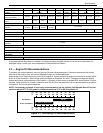
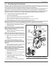
3. Remove carburetor fuel hose from outlet port. See Figure 2-3.
4. Remove screw at front of power wire connector and pull connector from fuel solenoid.
5. Expand spring clamp on fuel enrichment hose and remove from hose barb.
NOTE: On 5.4L (48 kW) units, remove two screws (with flat washers, lock washers and hex nuts) to release fuel
inlet flange from frame rail. This will provide adequate access to the regulator for jet conversion.
6. Remove black pipe assembly from outlet port. If clearance is not sufficient, first remove fuel solenoid assembly.
7. Rotate NG fuel jet counterclockwise to remove
from the outlet port.
NOTE: Both the NG and LP fuel jets are slotted, so
that they may be removed and installed using an
ordinary flat blade screwdriver.
8. Rotate LP fuel jet counterclockwise to remove
from the jet keeper port.
NOTE: The orifice size is stamped on each jet. The
jet with the larger orifice is used for running on NG.
9. Rotate LP fuel jet clockwise to install in the outlet
port.
10. Rotate NG fuel jet clockwise to install in the jet
keeper port.
11. Install fuel solenoid assembly, if removed.
NOTE: Solenoid must be installed with flow arrow
pointed toward black pipe assembly. See inset of
Figure 2-3.
12. Apply appropriate pipe sealant to threads of black
pipe assembly and install into outlet port.
NOTE: On 5.4L (48 kW) units, install two screws
(with flat washers, lock washers and hex nuts) to
fasten fuel inlet flange to frame rail.
13. Expand spring clamp on fuel enrichment hose
and install onto hose barb.
14. Push power wire connector onto fuel solenoid and
install screw.
15. Install carburetor fuel hose onto outlet port.
16. Install battery negative cable (black) onto battery
negative (-) terminal.
17. Turn on the main gas supply.
18. See Subsection 2.7.2—Change Fuel Selection.
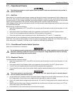
Figure 2-3. Demand Regulator Assembly
Spring
Carburetor
Connector
Fuel
Black
Fuel Jet
Outlet Port
Jet Keeper
Screw
Fuel Hose
Solenoid Body
Enrichment
Hose
Clamp
Pipe
Assembly
Port