


7
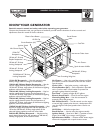
10000EXL Extended Life Generator
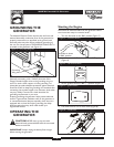
GROUNDING THE
GENERATOR
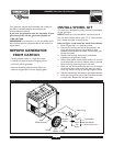
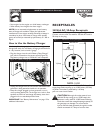
The National Electrical Code requires that the frame and
external electrically conductive parts of this generator be
properly connected to an approved earth ground. Local
electrical codes may also require additional grounding of
the unit. For that purpose, a GROUNDING WING NUT is
provided on the generator end (Figure 4).
Generally, connecting a No. 12 AWG (American Wire
Gauge) stranded copper wire to the grounding wing nut
and to an earth–driven copper or brass grounding rod
(electrode) provides adequate protection against electrical
shock. Be careful to keep the grounding wire attached after
connecting the stranded copper wire. However, local codes
may vary widely. Consult with a local electrician for
grounding requirements in your area.
Properly grounding the generator helps prevent electrical
shock if a ground fault condition exists in the generator or
in connected electrical devices, especially when the unit is
equipped with a wheel kit. Proper grounding also helps
dissipate static electricity, which often builds up in
ungrounded devices.
OPERATING THE
GENERATOR
CAUTION! NEVER start or stop unit with
electrical loads connected AND with the connected
devices turned ON.
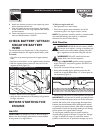
IMPORTANT:Always unplug the battery float charger
before starting the generator.
Starting the Engine
Disconnect all electrical loads from the generator. Follow
start instruction steps in numerical order:
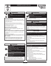
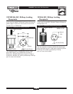
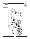
1. Turn the fuel valve to the “On” position (Figure 5).
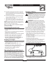
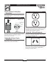
2. Make sure the Idle Control switch is in “Off” position
(Figure 6).
3. Set the Ignition switch to “On” (–) position (Figure 7).
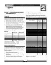
4. Pull choke control out to close choke (Figure 8).
Figure 5 — Fuel Shut-off Valve
Figure 7 — Ignition Switch
Figure 8 — Choke Lever
Figure 6 — Idle Control Switch
Figure 4 — Grounding Wing Nut
Grounding
Wing Nut
Fuel Valve is shown
in “On” position