


4
1.1 UNPACKING
Remove all packaging material.•
Remove separate accessory box.•
Remove the generator from carton.•
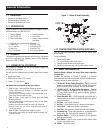
1.1.1 ACCESSORY BOX
Check all contents. If any parts are missing or damaged, locate an
authorized dealer at 1-888-436-3722.
1 - Owner’s Manual • 1 - Handle Assembly•
1 - Liter Oil SAE 30 • 1 - Frame Foot•
2 - Never-Flat Wheels • 1 - Battery Charger (electric •
start only)
1 - Hardware Bag (containing the following):•
• 2-Rubber Feet • 2-M8 Bolt (Long)
• 2-1/2” Axle Pins • 2-M8 Bolts (Short)
• 2-Cotter Pins • 2-M8 Acorn Nut
• 2-1/2” Flat Washers • 4-Hex Flanged M8 Nuts
1.2 ASSEMBLY
The generator requires some assembly prior to using it. If problems
arise when assembling the generator, please call the Generator
Helpline at 1-888-77LOWES.
1.2.1 ASSEMBLING THE ACCESSORY KIT
The wheels are designed into the unit to greatly improve the
portability of the generator.
You will need the following tools to properly install the accessory
kit.
Needle Nose Pliers•
Ratchet and a 13mm (1/2”) socket •
13mm (1/2”) box wrench•
NOTE:
The wheels are not intended for over-the-road use.
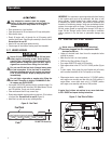
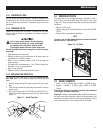
1. Refer to Figure 1 and install the Wheels as follows:
• Slide the Axle Pins through the Wheel, 1/2" Flat Washer, and Wheel
Bracket on the frame.
• Insert the Cotter Pin through the Axle Pin then bend the tabs (of the
Cotter Pins) outward to lock into place.
2. Refer to Figure 1 and install the Frame Foot and Rubber
Bumpers as shown.
• Slide the Rubber Bumper studs through the Frame Foot then install
the Locking Flange Nuts.
• Slide the Hex Head Bolts through the holes in the Frame Rail.
• Slide the Frame Foot onto the Hex Head Bolts then install the
Locking Flange Nuts.
3. Refer to Figure 1 and install the Handle as shown.
• Slide the long Bolts through the Handle Bracket and Handle, then
install the Hex Nuts.
Figure 1 – Wheel & Handle Assembly
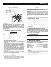
1.2.2 STARTER CONNECTION (ELECTRIC START ONLY)
The unit has been deliberately shipped with the starter cable
disconnected.
To connect starter:
1. Locate starter cable.
2. Pull vinyl boot back onto starter cable.
3. Remove nut and washer from starter post.
4. Put starter cable onto post and re-install washer and nut.
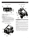
2.1 KNOW THE GENERATOR
Read the Owner’s Manual and Safety Rules before operating
this generator.
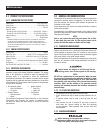
Compare the generator to Figures 2 through 4 to become
familiarized with the locations of various controls and adjustments.
Save this manual for future reference.
1. 120 Volt AC, 20 Amp, Duplex Receptacle – Supplies electrical
power for the operation of 120 Volt AC, 20 Amp, single-phase,
60 Hz electrical lighting, appliance, tool and motor loads.
2. 120/240 Volt AC, 30 Amp Locking Receptacle – Supplies
electrical power for the operation of 120 and/or 240 Volt AC,
30 Amp, single-phase, 60 Hz, electrical lighting, appliance,
tool and motor loads.
3. Circuit Breakers (AC) – Each receptacle is provided with a
push-to-reset circuit breaker to protect the generator against
electrical overload.
4. Oil Drain – Use to drain engine oil.
5. Air Filter – Filters intake air as it is drawn into the engine.
6. Choke Knob – Used when starting a cold engine.
7. Fuel Tank – See generator Specifications for tank capacity.
8. Grounding Lug – Ground the generator to an approved earth
ground here. See "Grounding the Generator" for details.
9. Run/Stop Switch – Controls the operation of the generator
(pull start models only).
9A. Start Switch – Used to start engine from the starter motor
(electric start models only).
10. Muffler – Quiets the engine.
General Information