


4
1.1 UNPACKING
• Remove all packaging material.
• Remove separate accessory box.
• Remove the generator from carton.
1.1.1 ACCESSORY BOX
Check all contents. If any parts are missing or damaged, locate an
authorized dealer at 1-888-436-3722.
• 1 - Owner’s Manual
• 1- Oil SAE 30
• 2- 7” Wheels
• 1- Handle Assembly
• 1- Handle Bracket
• 1- Wheel Axle
• 1- Hardware Bag (containing the following):
2 - Rubber bumpers 7 - M6 Flange Nuts
2 - Bumper Brackets 2 - Cotter Pins
2 - M12 Flat Washers 2 - Hubs
5 - M6-1 x 40 Flange Bolts 2 - M6-1.0 x 16 Flange
Bolts
1.2 ASSEMBLY
The generator requires some assembly prior to using it. If problems
arise when assembling the generator, please call the Generator
Helpline at 1-888-436-3722.
1.2.1 ASSEMBLING THE ACCESSORY KIT
The wheels are designed to greatly improve the portability of the
generator.
NOTE:
The wheels are not intended for over-the-road-use.
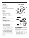
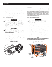
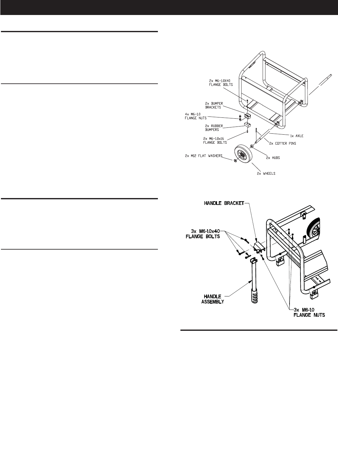
1. Refer to Figure 1 to install the wheels as shown.
• Slide the axle through the frame brackets.
• Slide on the hub, wheel and flat washer, then insert the
cotter pin through the wheel axle hole.
• Bend the cotter pin tabs outward to lock the pin in place.
2. Refer to Figure 1 to install the rubber bumpers as shown.
• Insert an M6 bolt through the rubber bumper and the
bottom of the bumper bracket. Secure the bolt with an M6
flange nut.
• Install an M6 bolt through the generator frame and
through top of the bumper bracket. Secure the bolt with
an M6 flange nut.
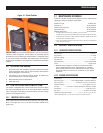
3. Refer to Figure 2 to install the handle assembly as shown.
• Insert the handle bracket onto the generator frame and
secure with two M6 bolts and two M6 flange nuts.
• Align the handle assembly holes with the handle bracket
holes and secure with one M6 bolt and one M6 flange nut.
To properly install the accessory kit, the following tools are needed:
• Pliers
• 8 mm Box Wrench
• 10 mm Box Wrench
Figure 1 – Wheel Assembly
Figure 2 – Handle Kit
2.1 KNOW THE GENERATOR
Read the Owner’s Manual and Safety Rules before
operating this generator.
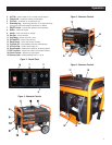
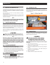
Compare the generator to Figures 3 through 6 to become familiarized
with the locations of various controls and adjustments. Save this
manual for future reference.
1. 120 Volt AC, 20 Amp, GFCI Receptacle – Supplies electrical
power for the operation of 120 Volt AC, 20 Amp, single-phase,
60 Hz electrical lighting, appliance, tool and motor loads. It
also provides protection with an Integral Ground Fault Circuit
Interrupter with press to "Test" and "Reset" buttons.
2. Circuit Breakers (AC) – Each receptacle is provided with a
13.5A push-to-reset circuit breaker to protect the generator
against electrical overload.
General Information