


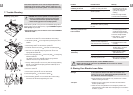
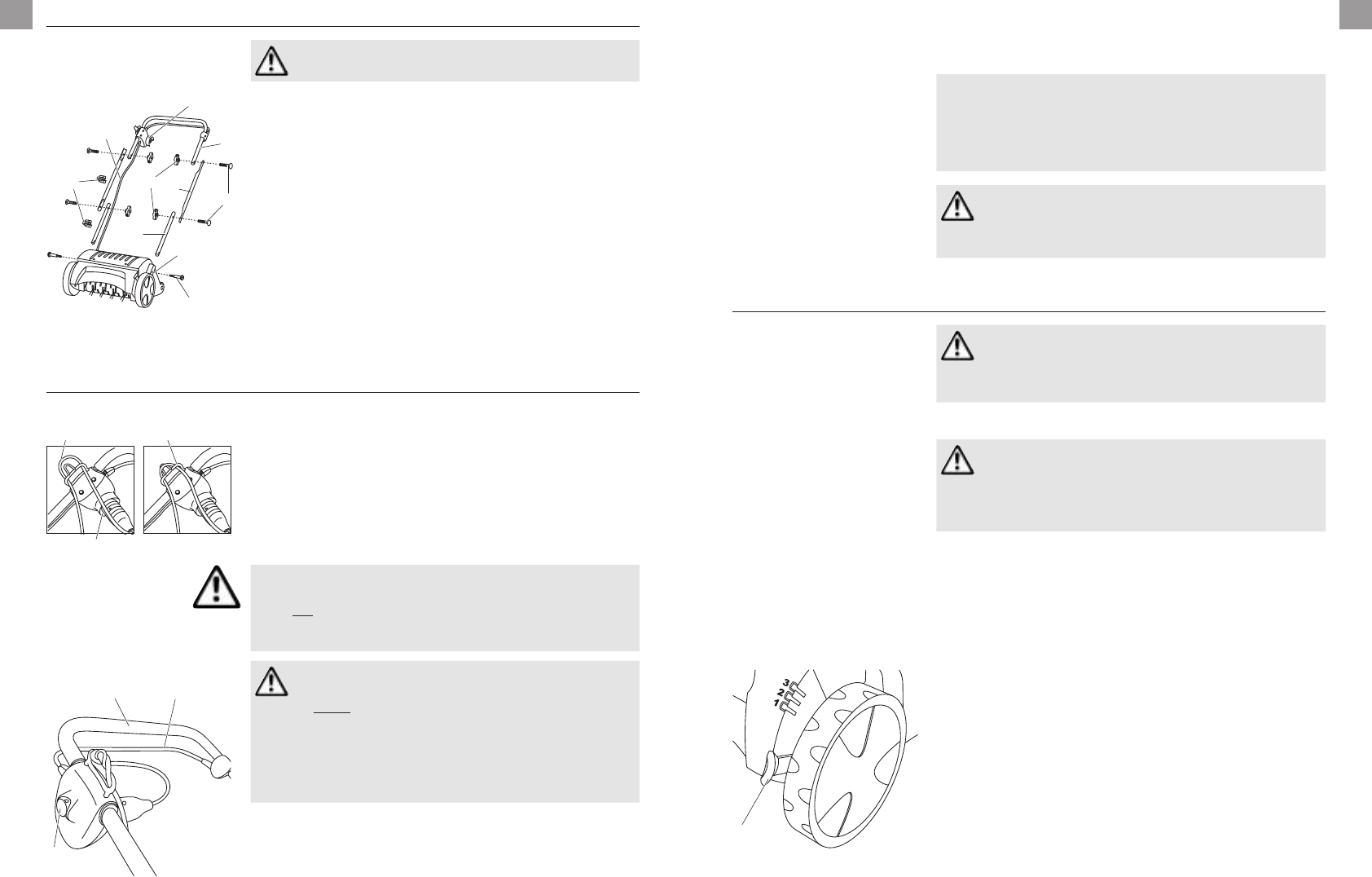
4. Assembly
Assembling the handle:
3
9
6
5
1
2
4
c
8
7
v Do not place the connecting cable
8
under strain
during assembly.
1. Insert the two lower sections of the upright
5
(with the end
with the round hole) in the mountings in the motor casing
6
and secure with the crosshead screws
9
.
2. Insert the two locking bolts
1
from outside through the holes
in the two central sections
2
of the upright and secure to the
lower sections of the upright
5
with two wing nuts
4
.
3. Screw the upper part of the upright with starting handle
3
to
the central sections of the upright
2
with two more locking
bolts
1
and the wing nuts
4
.
This completes the assembly of the handle.
Warning: Fit the upper section of the upright with starting
handle
3
in such a way that the plug
7
with the power
cable
8
is on the right side (in direction of movement)
(seefig.).
4. Attach connection cable
8
to the handle with the two cable
clips
c
.
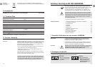
5. Operation
Connecting extension cable:
0 A
7
1 2
1. Push connector of extension cable
0
on to the plug
7
.
2. Draw a loop of the extension cable
0
through the cable strain
relief device
A
1 and suspend in position 2.
This prevents inadvertent disconnection of the plug and socket
connection.
3. Insert extension cable
0
into a mains socket.
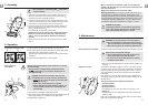
Starting Electric
Lawn Rake:
Danger of injury if the Electric Lawn Rake does not switch
off auto matically!
v Do not remove or bridge safety devices fitted to the
Electric Lawn Rake (e.g. by tying the starting lever to
theupper handle)!
3
B
C
DANGER! The Electric Lawn Rake does not stop
immediately after the motor has been switched off:
v Never lift, tip or carry the Electric Lawn Rake with
the motor running!
v Never start on solid ground (e.g. asphalt).
v Always maintain the safety distance between the
aerator cylinder and the user as defined by the
guide handle.
1. Place Electric Lawn Rake on flat grass surface.
2. Keep safety interlock
B
pressed down and pull starting lever
C
on the upper handle
3
. The Electric Lawn Rake starts.
3. Release safety interlock
B
.
When in operation, the extension cable
0
must always be
guided in the direction you are working and to the side of the
area to be worked on.
Always work away from the connection cable.
Blockage Protection: If the aerator cylinder is blocked, e.g. by
a foreign body, immediately release the starting lever. If the
blockage lasts longer than 10 seconds and the starting lever has
not been released, blockage protection is activated. In this case
immediately release the starting lever. The Lawn Rake can be
switched on again after cooling down for approx. 1 minute.
DANGER OF INJURY!
If blockage protection is activated and the starting
lever is not released, the Electric Lawn Rake starts
again automatically after approx. 1 minute.
6. Maintenance
DANGER! The aerator cylinder can cause injuries!
v Prior to maintenance, unplug from the mains and
wait until the Electric Lawn Rake drum has stopped.
v Wear working gloves for performing maintenance.
Cleaning Electric Lawn Rake: The Electric Lawn Rake should be cleaned after each time it is used.
Risk of injury and physical damage!
v Do not clean Electric Lawn Rake under running
water (particularly under high pressure).
v Do not use hard or pointed objects for cleaning
theElectric Lawn Rake.
v Remove grass and deposits from wheels, aerator cylinder and
housing.
Adjusting for wear:
D
The Electric Lawn Rake is subject to wear in use due to the way
in which it works. The more intensively the Electric Lawn Rake is
used, the greater the wear on the spring tines. Hard or very dry
ground accelerates wear as does excessive use of the Electric
Lawn Rake.
If the results of your work with the Electric Lawn Rake become
increasingly worse due to knife wear, the aerator cylinder can be
adjusted twice.
The aerator cylinder has 4 adjustment positions:
• Transport position
• Aerating position 1
• Aerating position 2:
If the springs are worn (the rake roller is lowered by 3 mm).
• Setting 3:
Second setting for worn springs (the rake roller is lowered by
afurther 3 mm).
Push wear compensation lever
D
gently away from the housing
and move to the position required.
14
GB
15
GB