Troubleshooting, Adjustment & Service
CUTTING HEIGHT ADJUSTMENT
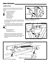
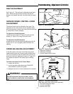
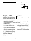
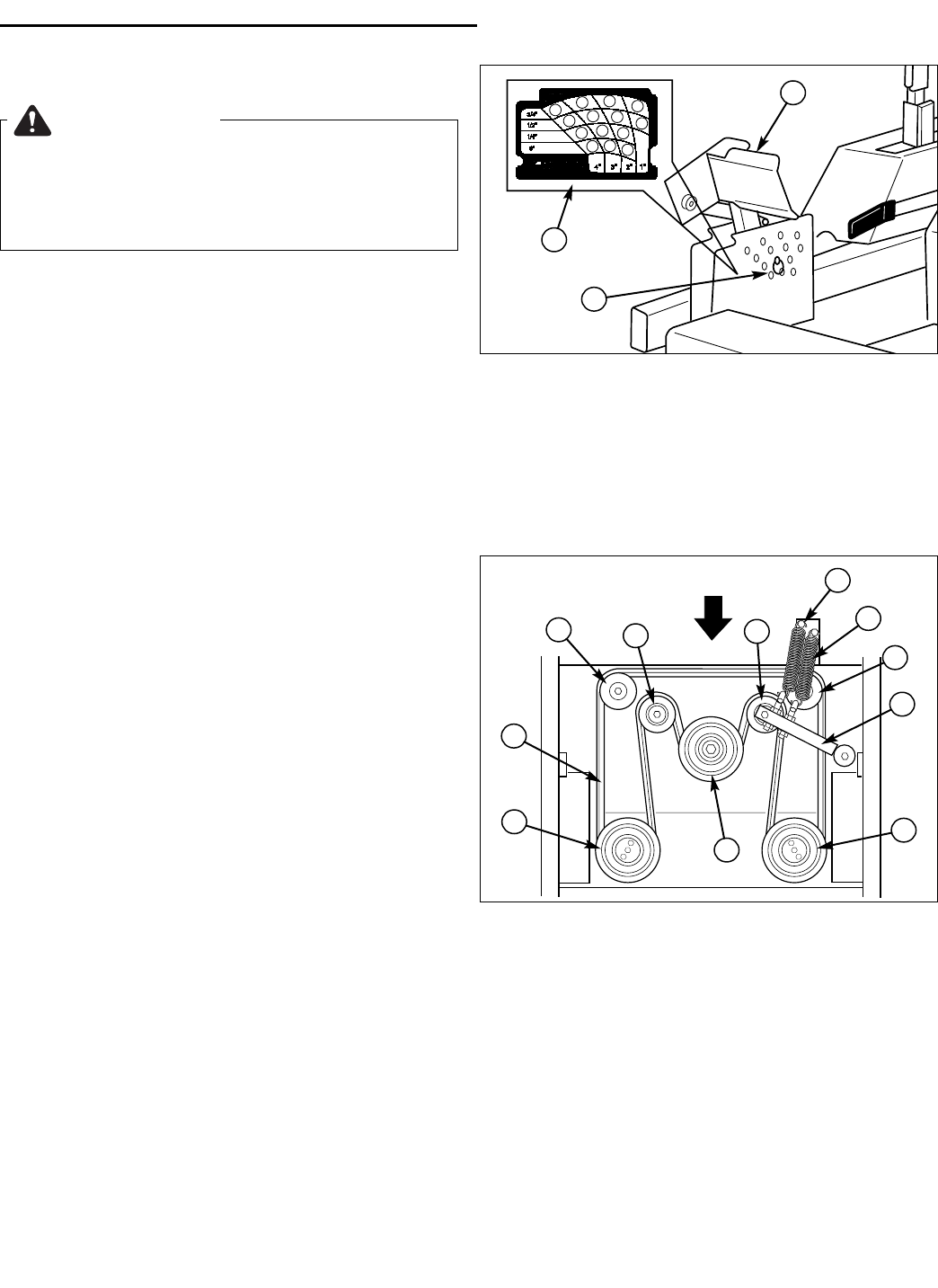
The cutting height adjustment pin (A, Figure 28) controls
the mower cutting height. The cutting height is
adjustable between 1-3/4” (4.4cm) and 5” (12.7cm) in
1/4” (.64cm) increments.
Depress the deck lift foot pedal (B, Figure 28), placing
the majority of the force on the top edge of the pedal
until it locks into the “TRANSPORT” position. Place the
cutting height adjustment pin in the desired cutting
height. Depress the deck lift foot pedal, placing the
majority of the force on the bottom edge of the pedal to
release the pedal from the “TRANSPORT” position.
WARNING
Before checking mower, shut off PTO and engine.
Allow all moving parts to stop. Remove ignition
key, then disconnect the spark plug wire and
fasten it away from the spark plug.
A
B
C
Figure 28. Cutting Height Adjustment
A. Cutting Height Adjustment Pin
B. Deck Lift Foot Pedal
C. Cutting Height Selection Decal
25
HYDRAULIC PUMP DRIVE BELT
REPLACEMENT
1. Park the tractor on a smooth, level surface such as a
concrete floor. Disengage the PTO, engage the
parking brake, turn off the engine, and remove the
ignition key.
2. Remove the PTO drive belt (see MOWER BELT
REPLACEMENT for removal instructions).
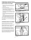
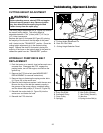
3. Remove the nuts fastening the spring anchor bolts
(H, Figure 29) to the anchor arm.
4. Remove the old belt and replace it with the new one.
Be sure the ribs of the belt are seated correctly in
the grooves of the pump pulleys, crankshaft pulley
and the ribbed idler pulleys (C, B and E, Figure 29).
5. Reinstall the anchor bolts (H, Figure 29) into the
anchor arm and fasten the nuts.
6. Reinstall the PTO drive belt.
FRONT
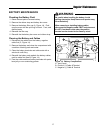
Figure 29. Hydraulic Pump Drive Belt Replacement
A. Pump Drive Belt E. Idler Pulley (Ribbed)
B. Crankshaft Pulley F. Idler Pulley (Smooth)
C. Pump Pulley G. Idler Arm
D. Spring(s) H. Spring Anchor Bolt(s)
A
E
B
C
C
F
D
H
E
G
F


