


Troubleshooting, Adjustment & Service
DECK LIFT ROD TIMING
ADJUSTMENT
1. Park machine on a flat, level surface. Disengage the
PTO, stop the engine and engage the parking brake.
Rear tires must be inflated to 18 psi (1,24 bar); front
tires to 25 psi (1,72 bar).
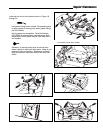
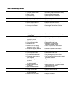
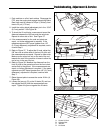
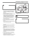
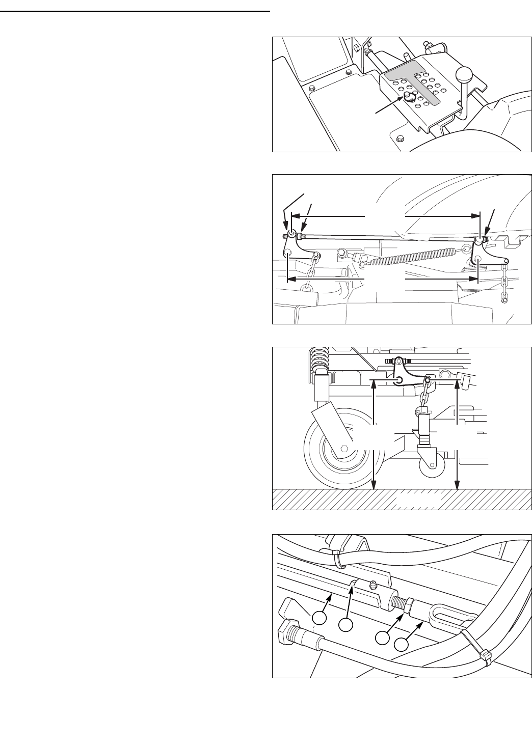
2. Install the cutting height adjustment pin in the 3-3/4”
(9,5 cm) position. See Figure 36.
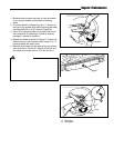
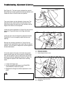
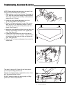
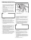
3. To check the lift rod timing, measure and record the
distance between the lift pivots and the rod pivots.
Repeat for other side of unit. See Figure 37.
4. If the measurements for the rods and pivots are
equal,, no further adjustment is required. If the
measurements are NOT equal (greater than 1/8”
(3,17mm) difference), adjustment is required, contin-
ue with Step 5.
5. Refer to Figure 37. To adjust the lift rods, adjust the
5/8” hex nuts on either side of the front lift pivot until
the measurements are equal. Repeat for other side.
Make sure the nylon lock nut on the end of the rod
towards the rear of the machine is loose to allow the
rod to turn in the rear lift pivot.
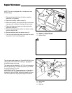
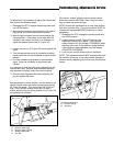
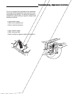
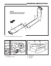
6. Refer to Figure 38. Measure the distance from the
front lift pivot to the ground and from the front chain
anchor bolt to the ground. If the measurements are
equal, no further adjustment is required. If the meas-
urements are NOT equal (greater than 1/8” (3,17mm)
difference), adjustment is required, continue with
Step 7.
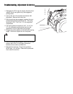
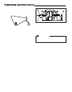
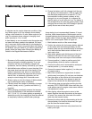
7. Raise the seat plate to access the center lift link (A,
Figure 39).
8. Loosen the jam nut (C) on the lift clevis (D) and turn
the adjuster bolt (B) until the measurements are
equal. Tighten the jam nut against the lift clevis.
3-3/4"
(9,5 cm)
Figure 36. Deck Height Pin Position
Figure 38. Measure Front Lift Pivot
GROUND
Measure
First
Measure
Second
Figure 39. Center Lift Link Adjustment
A. Center Lift Link
B. Adjuster Bolt
C. Jam Nut
D. Lift Clevis
B
C
D
A
Measure
First
Measure
Second
Adjust
Here
Keep
Loose
Figure 37. Measure & Adjust Lift Rod Timing
31