


29
Troubleshooting, Adjustment & Service
NEUTRAL POSITION AND RETURN
SPRING ADJUSTMENT
To determine if it is necessary to adjust the neutral posi-
tion, perform the following steps.
1. Disengage the PTO, engage the parking brake and
turn off the engine.
2. Move the ground speed control levers in the operat-
ing position, pull levers rearward and release.
3. Move the ground speed control levers towards the
neutral position. If the levers do not align with the
notches in the neutral lock plate, it is necessary to
adjust the reverse return bolts (A, Figure 32).
Neutral Position Adjustment
1. Loosen the jam nut (D, Figure 32) locked against the
clevis.
2. Turn the reverse return bolt (A) clockwise to adjust
handle rearward, counter-clockwise to adjust handle
forward.
4. Pull lever rearward and release to check position
again. Adjust as necessary to align levers with
notches.
It is important to note that after every adjustment of the
reverse return bolt, the lever must be pulled rearward
and released to properly check the neutral position.
5. Once the lever alignment has been adjusted, lock
jam nut against the clevis.
Return Spring Adjustment
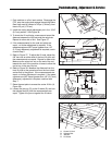
After adjusting the neutral position, lock the levers in the
neutral position and measure the reverse return spring
(B, Figure 32) length. This should be 2-3/8” (6,03 cm)
long. If not, hold the reverse return bolt (A) with a
wrench while turning the spring position nut (C) until the
measurement is achieved.
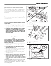
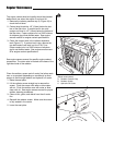
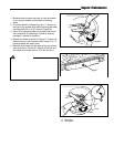
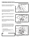
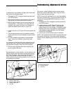
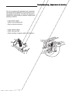
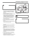
Figure 32. Neutral Spring Return Adjustment
A. Reverse Return Bolt
B. Reverse Return Spring
C. Spring Position Nut
D. Jam Nut
A
B
D
C
NEUTRAL ADJUSTMENT
If the tractor “creeps” while the ground speed control
levers are locked in NEUTRAL, then it may be neces-
sary to adjust the control linkage.
NOTE: Perform this adjustment on a hard, level surface
such as a concrete floor. The neutral position MUST be
checked and adjusted BEFORE performing a neutral
adjustment.
1. Disengage the PTO, engage the parking brake and
turn off the engine.
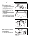
2. Loosen the jam nuts (B, Figure 33) and turn the
adjustment linkage (A) to adjust. If the machine
creeps forward, turn the linkage CLOCKWISE (while
standing at the rear of the machine, facing forward),
if the machine creeps backward, turn the linkage
COUNTER-CLOCKWISE.
3. Lock the jam nuts (B) when neutral is achieved.
NOTE: This adjustment should NOT be performed while
the machine is running. It may take several attempts to
achieve neutral, depending upon how much the machine
creeps.
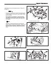
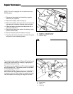
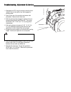
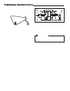
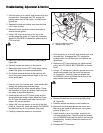
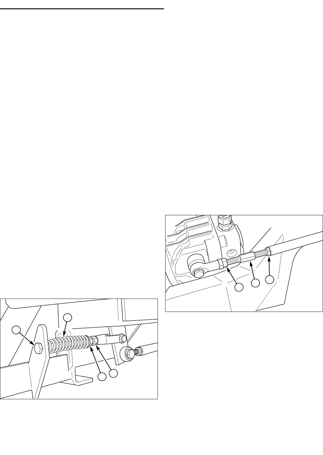
Figure 33. Neutral Adjustment
(Left-hand side shown)
A. Control Linkage
B. Jam Nuts
B
B
A