


23
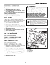
Troubleshooting, Adjustment & Service
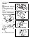
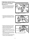
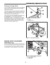
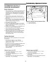
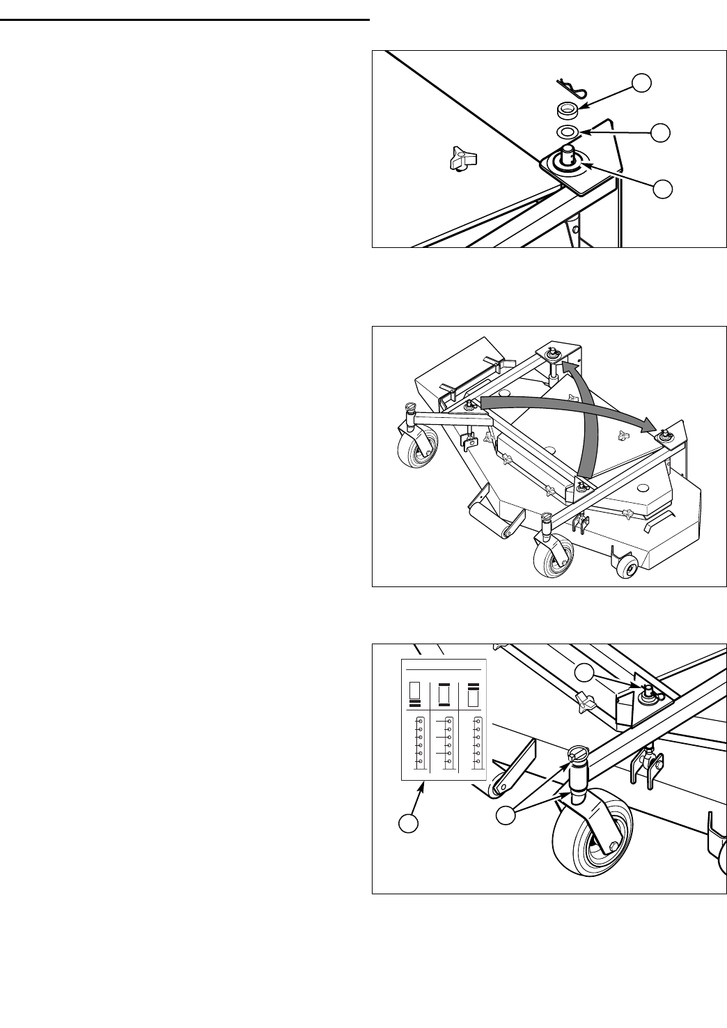
Figure 20. Shim Assembly Position
A. Shim
B. Spacer
C. Retaining Collar
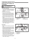
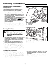
Figure 21. Proper Shim Location
B
Shimming the Hanger Shafts
Once it has been determined that a shim (P/N 20928) is
required, you first must determine which rear hanger
shaft requires the shim.
The shim (A, Figure 20) must be placed in between the
spacer (B, Figure 20) and the retaining collar (C, Figure
20) on the OPPOSITE side from which the front shaft
has movement or slack (see Figure 21).
Once the shim has been assembled in the proper loca-
tion, repeat Step 2 - 8 in the
DECK LEVELING
ADJUSTMENT
section. This adjustment may need to
be repeated more than once until the proper number of
shims has been installed to obtain the proper cutting
height, equal measurements from side to side and no
movement of the front hanger shafts.
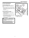
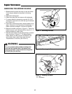
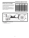
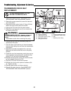
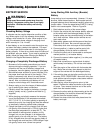
Figure 22. Mowing Height Adjustment
A. Height Selection Decal
B. Caster Spacer
C. Hairpin Clip
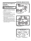
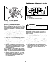
46028
CUTTING HEIGHT
CASTER SPACER PLACEMENT
2-1/4
2-3/4
3-1/4
3-3/4
4-1/4
4-3/4
2
2-1/2
3
3-1/2
4
4-1/2
1-3/4
2-1/4
2-3/4
3-1/4
3-3/4
4-1/4
MOWING HEIGHT ADJUSTMENT
(DDSH Models only)
Refer to the Height Selection decal (A, Figure 22) locat-
ed on the deck hanger frame and adjust the positions of
the caster spacers and hairpins to obtain the desired
mowing height. Perform adjustment to all four shafts.
A
A
C
B
C