


24
Troubleshooting, Adjustment & Service
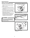
MOWER BELT REPLACEMENT AND
ADJUSTMENT
PTO Clutch to Deck Belt
1. Park the machine on a smooth, level surface such as
a concrete floor. Disengage the PTO, engage the
parking brake, turn off the engine, and remove the
ignition key.
2. Remove the mower deck guard.
3. Remove the rear engine deck guard.
4. Loosen the wing nut (C, Figure 23) to release the
belt tension on the deck drive belt (B, Figure 23).
5. Slide the drive belt over the edge of the spindle pul-
ley and then slide the belt around the idler pulley.
Drop the belt from the PTO clutch pulley groove.
6. Remove the old belt and replace with a new one.
Make sure the V-side of the belt runs in the pulley
grooves.
7. Install the drive belt on the PTO pulley, the idler pul-
ley and center spindle pulley. Tighten the wing nut
(C, Figure 23) until a 10 lb. (44.5 newton) force is
required to deflect the belt 1/2” (1,27cm) between the
idler pulley and center spindle pulley. Jam hex nut
(D, Figure 23) against anchor. See Figure 23.
8. Run the mower under no-load condition for about 5
minutes to break-in the new belt and re-check belt
tension. Adjust if necessary.
Spindle Belt
1. Remove PTO clutch to Deck belt. See instructions
above.
2. Loosen the nylon nut (C, Figure 24) to release the
belt tension on the spindle drive belt (B, Figure 24).
3. Slide the drive belt over the edge of one of the spin-
dle pulleys and then slide the belt around the idler
pulley and remaining spindle pulleys.
4. Remove the old belt and replace with a new one.
Make sure the V-side of the belt runs in the pulley
grooves (for single v-section belts).
5. Install the spindle drive belt on the spindle pulleys
and the idler pulley. Tighten the nylon nut (C, Figure
24) until a 10 lb. (44.5 newton) force is required to
deflect the belt 1/2” (1,27cm) between the idler pulley
and right-hand spindle pulley. See Figure 24.
6. Run the mower under no-load condition for about 5
minutes to break-in the new belt and re-check belt
tension. Adjust if necessary.
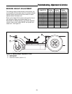
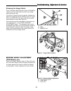
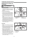
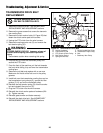
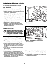
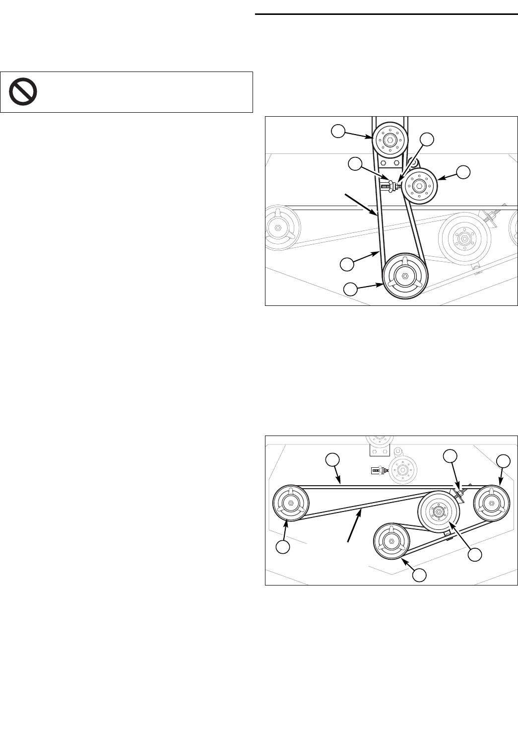
Figure 23. PTO Clutch to Deck Belt
A. Stationary Idler Pulley D. Hex Nut
B. Deck Drive Belt E. Adjustable Idler Pulley
C. Wing Nut F. Center Spindle Pulley
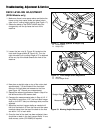
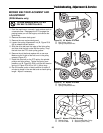
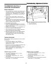
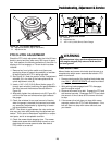
Figure 24. Spindle Drive Belt
A. Spindle Pulley
B. Spindle Drive Belt
C. Nylon Lock Nut
D. Idler Pulley
A
B
E
F
B
A
Check
Tension Here
Check
Tension Here
D
C
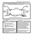
A
A
C
D
To avoid damaging belts, DO NOT
PRY BELTS OVER PULLEYS.