


00
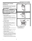
Features & Controls
of the Zero Turn Rider
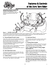
A. Ground Speed Control Levers
These levers control the ground speed of the rider. The
left lever controls the left rear drive wheel and the right
lever controls the right rear drive wheel.
Moving a lever forward increases the FORWARD speed
of the associated wheel, and pulling back on a lever
increases the REVERSE speed.
Note: The further a lever is moved away from the neutral
position the faster the drive wheel will turn.
See the Operating the Zero Turn Rider section, page 14,
for steering instructions.
B. Seat Adjustment Lever
The seat can be adjusted forward and back. Move the
lever forward, position the seat as desired, and release
the lever to lock the seat in position.
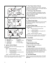
C. Control Panel
The control panel houses the starting, engine speed and
PTO controls. See Page 8 for more details.
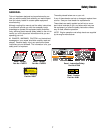
Figure 1. CONTROL FUNCTIONS
The information below briefly describes the function of the individual controls. Starting, stopping, driving, and mow-
ing require the combined use of several controls applied in specific sequences. To learn what combination and
sequence of controls to use for various tasks see the OPERATION section.
Please take a moment and familiarize
yourself with the name, location, and
function of the following. This will
enable you to understand the safety and
operating instructions provided in this
manual.
D. Instrument Panel
The instrument panel shows a variety of engine opera-
tion and status information. See Page 8 for more
details.
E. Parking Brake Handle
The parking brake is applied by pulling UP on the park-
ing brake handle until it locks over-center. To release
the parking brake, push the handle DOWN.
F & G. Deck Lift Pedal & Cutting Height
Adjustment Pin
These control the cutting height of the mower deck.
Depress the pedal until it locks into the TRANSPORT
position. Place the adjustment pin in the desired cutting
height and release the lift pedal.
H. Fuel Tank Selection Valve (Gas Model Only)
Turning the handle to the desired position determines
which tank will be supplying fuel. With the handle point-
ing towards the left, it will draw fuel from the left-hand
tank. With the handle pointed towards the right, it will
draw fuel from the right-hand fuel tank. With the handle
pointing towards the operator, it will shut off fuel flow to
the engine.
A
F
G
E
C
B
A
D
H
8