


24
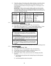
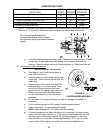
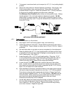
LUBRICATION CHART
FITTING
LOCATIONS
INITIAL
PUMPS
NO. of
PLACES
SERVICE
INTERVAL
1. Front Caster wheel hubs w/o Zerk
∗0
2
∗yearly
2. Front Caster Pivots
∗0
2
∗yearly
3. Height Adjustment Shaft Bearings 1 5 40 hours
4. Deck Drive Belt Idler Arm 1 1 yearly
5. Pump Drive Belt Idler Arm 1 1 yearly
∗ See 4.1.14 Section c) for special lubrication instructions on the front caster pivots and
Section 4.1.15 for special lubrication instructions on the front caster wheel hubs.
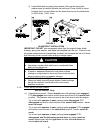
c) Lubricate front caster pivots once a year. Remove hex plug and cap. Thread
grease zerk in hole and pump with grease until it oozes out around top
bearing. Remove grease zerk and thread plug back in. Place cap back on.
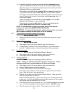
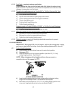
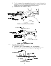
4.1.15 Lubricate caster wheel hubs:
Service Interval: Once Yearly
a) Stop engine, wait for all moving parts to
stop, and remove key.
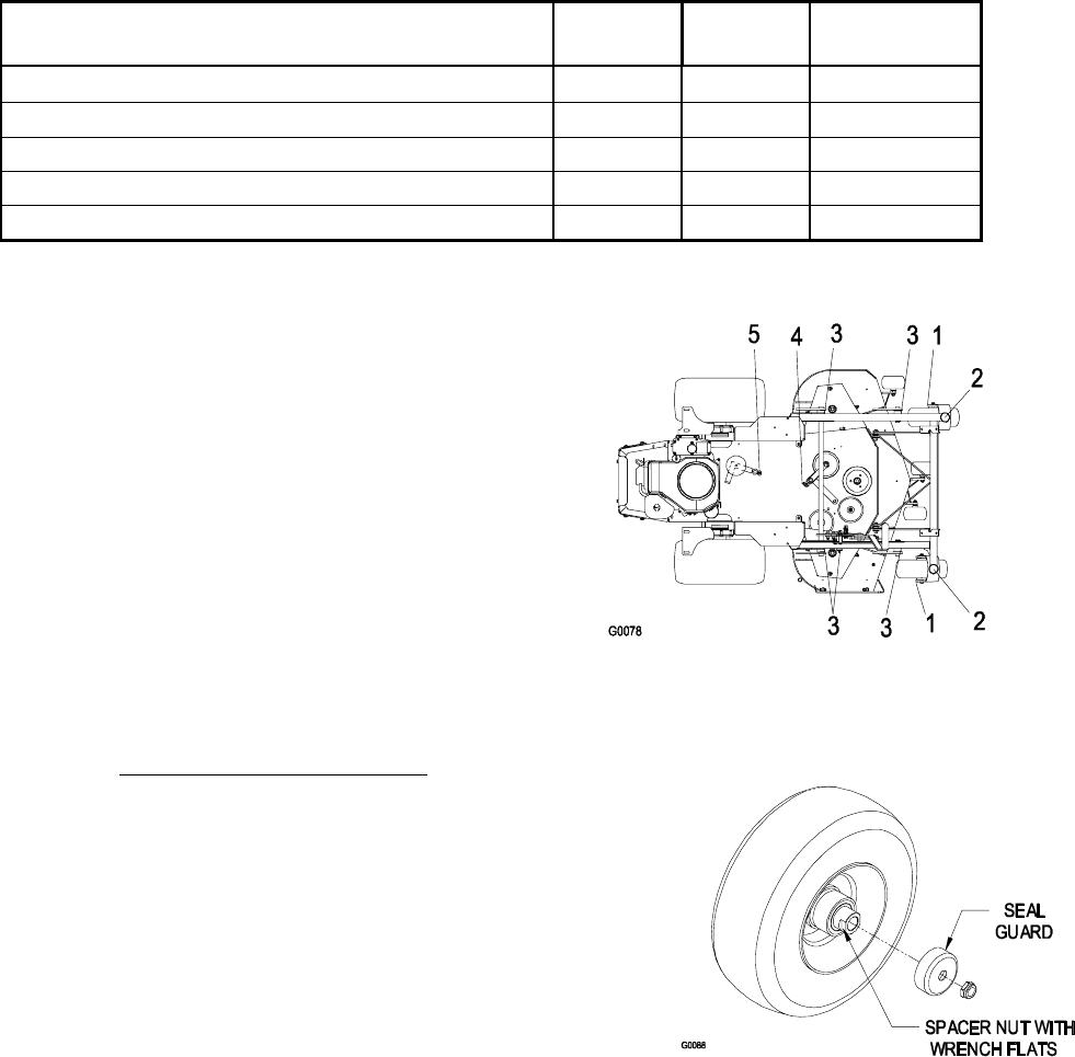
b) Remove caster bolt and caster wheel from
caster fork. Remove seal guards from the
wheel hub.
c) Remove one of the spacer nuts from the
axle assembly in the caster wheel. Note
that thread locking adhesive has been
applied to lock the spacer nuts to the axle.
Remove the axle (with the other spacer
nut still assembled to it) from the wheel
assembly.
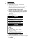
d) Pry out seals, and inspect bearings for wear or damage and replace if
necessary.
e) Pack the bearings with a NGLI grade #1 multi-purpose grease.
f) Insert (1) bearing, (1) new seal into the wheel.
NOTE: Seals (Exmark PN 103-0063) must be replaced.
g) If the axle assembly has had both spacer nuts removed (or broken loose),
apply a thread locking adhesive to (1) spacer nut and thread onto the axle
with the wrench flats facing outward. Do not thread spacer nut all of the
way onto the end of the axle. Leave approximately 1/8” (3 mm) from the
outer surface of the spacer nut to the end of the axle inside the nut.
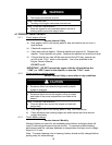
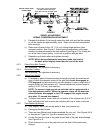
No. 5 (Pump Drive Belt Idler Arm)
Located Under Engine Frame - Grease
through hole in top of engine frame, between
pumps.
FIGURE 4
CASTER WHEEL ASSEMBLY