


13
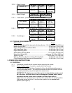
2.10.2 Overall Length:
48” Deck 52” Deck 60” Deck
Roll Bar - Up 73.9 in.
(187.7 cm)
75.5 in.
(191.8 cm)
77 in.
(195.6 cm)
Roll Bar - Down 79.6 in.
(202.2 cm)
81.2 in.
(206.2 cm)
82.4 in.
(209.3 cm)
2.10.3 Overall Height:
Roll Bar - Up Roll Bar - Down
69.4in. (176.3 cm) 51.3 in. (130.3 cm)
2.10.4 Tread Width: (center to center of tires, widthwise)
48” Deck 52” Deck
60” Deck
Drive Wheels
34.9 in.
(88.6 cm)
34.9 in.
(88.6 cm)
39.8 in.
(101.1 cm)
Front Casters
32.7 in.
(83.1 cm)
34.1 in.
(86.6 cm)
35.4 in.
(89.9 cm)
2.10.5 Wheel Base: (center of caster tire to center of drive tire)
48” Deck 52” Deck 60” Deck
46.2 in.
(117.3 cm)
46.2 in.
(117.3 cm)
48.8 in.
(124 cm)
2.10.6 Curb Weight: 48” Deck 52” Deck 60” Deck
874 lbs.
(396 kg)
887 lbs.
(402 kg)
978 lbs.
(444 kg)
2.11 TORQUE REQUIREMENTS
Bolt Location Torque
Cutter Housing Spindle Nut (secured with threadlocker) 140-145 ft-lbs. (190-197 N-m)
Blade Mounting Bolt ................................................................55-60 ft-lbs. (75-81 N-m)
Engine Deck/Front Frame Mount Bolts ...................................30-35 ft-lbs. (41-47 N-m)
Anti-Scalp Roller Nuts............................................................. 40-45 ft-lbs. (54-61 N-m)
Engine Mounting Bolts ...........................................................25-30 ft-lbs. (34-41 N-m)
Wheel Motor Mounting Bolts .................................................72-77 ft-lbs. (98-104 N-m)
Wheel Hub Slotted Nut ..................................................minimum 125 ft-lbs. (169 N-m)
Wheel Lug Nuts ..................................................................90-95 ft-lbs. (122-129 N-m)
Rollover Protection System (roll bar) Mounting Bolts ..............30-35 ft-lbs. (41-47 N-m)
Clutch Retaining Bolt (secured with threadlocker)...................55-60 ft-lbs. (75-81 N-m)
3. OPERATION INSTRUCTIONS
3.1 CONTROLS
3.1.1 Familiarize yourself with all controls before operating the mower.
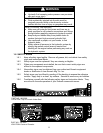
3.1.2 Motion Control Levers
: Located on each side of the console.
The left lever controls the flow of hydraulic oil from the left hydrostatic pump to
the left drive wheel motor. The right lever controls the flow of hydraulic oil from
the right hydrostatic pump to the right drive wheel motor.
IMPORTANT: To begin movement (forward or backward) the operator must
be in the seat, the brake lever must be disengaged (pushed down) before
the motion control levers can be moved in or the engine will kill.
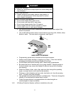
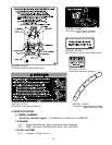
When levers are centered in the T-slot the drive system is in the neutral position.
With levers moved out in the T-slot the drive system is in the neutral lock
position (See Figure 2).