


- 27 -
5.2.4 Engine to Cutter Deck Belt
:
No adjustment necessary.
5.2.5 Transmission Belt Adjustment
:
a) Stop engine and wait for all moving parts to stop. Remove key or spark plug
wire(s).
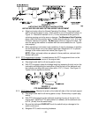
b) To tighten transmission belt, loosen the 3/8” nyloc nut on transmission belt
idler pulley. Slide bolt inward in slot and retighten nyloc nut.
c) When properly adjusted, the belt should have 1/2” (12 mm) of deflection with three
pounds (13.3 Nt) of pressure on the belt midway between the transmission and
engine pulley.
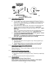
5.2.6 Wheel drive belts and scrapers
:
Be sure mud and grass scraper, on each side, is adjusted properly and centered in
the pulley grooves. The pointed part of the scraper should be centered and as
deep in the pulley groove as possible without rubbing at any point.
NOTE: Wheel drive springs have three tension settings. See Section 5.2.11.
5.2.7 Brake Adjustment
:
See 3.11 steps c) and d)
5.2.8 Wheel drive linkage adjustment
:
See 3.11 steps a) and b)
5.2.9 Shifter lever adjustment
:
See 3.10
5.2.10 Shifter detent adjustment
:
Transmission shifter detent can be adjusted by adjusting the setscrew on the
backside of transmission located just behind the neutral start switch. Turn setscrew
in (clockwise) to hold the transmission shifter more positively in each gear and to
increase the force on the lever required to shift gears.
Turn setscrew out (counterclockwise) to decrease force on lever required to shift
gears. Factory setting is to turn setscrew all the way in then back out 1-1/2 turns.
IMPORTANT: Screwing setscrew in too far will prevent the transmission from
shifting.
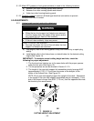
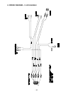
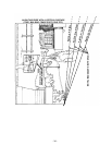
5.2.11 Wheel drive spring tension adjustment
:
It may be necessary to increase wheel drive belt tension under certain conditions
such as, wet grass, hilly terrain, or while pulling a sulky.
a) Stop engine, wait for all moving parts to stop, and remove key or spark plug
wire(s).
b) Disengage neutral lock/park brake latches and release drive levers to lower
spring force.
c) Remove the 5/16-18 whizlock nut securing the adjustment bolt to the drive
wheel shield. Locate bolt assembly in the desired position as follows
Position A - Normal Conditions
Position B - More Severe
Position C - Most Severe
NOTE: Lever force is lowest with bolt assembly in Position A and will increase in
Positions B and C (See Figure 15).